Nissan Murano. Manual - part 768


  Главная      Nissan     Nissan Murano (2014 year) - Service Manual


поиск по сайту            


содержание   ..  766  767  768  769   ..


Nissan Murano. Manual - part 768


FL-12

< REMOVAL AND INSTALLATION >

FUEL TANK

4.

Remove parking rear brake cables. Refer to 

PB-6, "Exploded View"

.

5.

Remove rear suspension member assembly. Refer to 

RSU-18, "Exploded View"

. (AWD models)

NOTE:
For this service, drive shaft, final drive, and rear suspension member are required not to be separate one
another during removal.

6.

Remove fuel tank protectors.
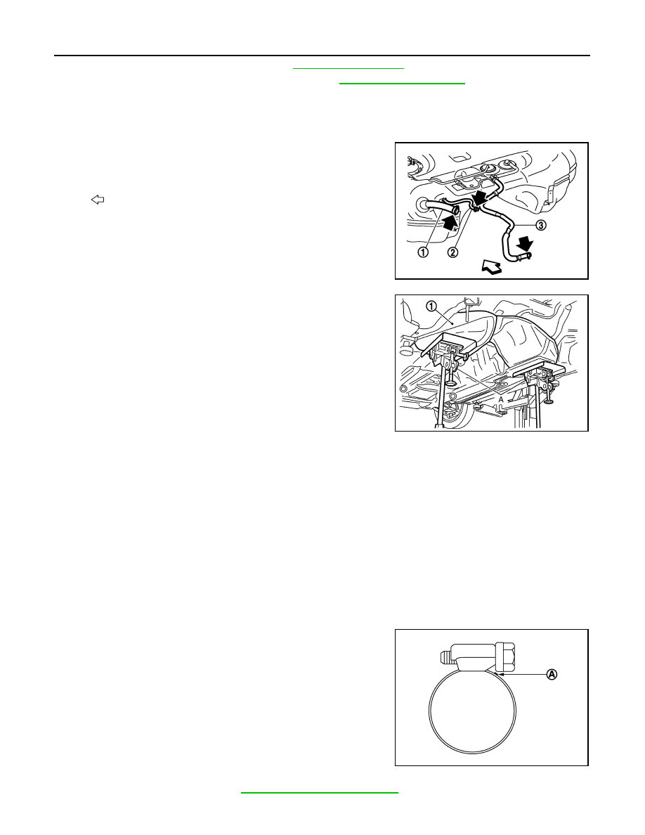
7.

Disconnect fuel filler hose (1), EVAP/Vent line hose (3), and
EVAP (Recirculation) hose (2) from the side other than the fuel
tank side.

8.

Support the lower part of fuel tank (1) with transmission jack (A).

CAUTION:

Support the position that fuel tank mounting bands never
engage.

9.

Remove fuel tank mounting bands.

10. Supporting with hands, descend transmission jack carefully, and remove fuel tank.

CAUTION:

• Check that all connection points have been disconnected.
• Confirm there is no interference with vehicle.

11. Remove fuel filler tube if necessary.

INSTALLATION

Note the following, and install in the reverse order of removal.
• Surely clamp fuel hoses and insert hose to the length below.

• Be sure hose clamp is not placed on swelled area of fuel tube.
• Tighten the clamp hand with the top mark (A) until the mark is on

the bolt head flange.

• To connect quick connector, refer to 

FL-6, "Removal and Installation"

.

: Vehicle front

JPBIA1696ZZ

JPBIA0145ZZ

Fuel filler hose 

: 35 mm (1.38 in)

The other hoses

: 25 mm (0.98 in)

JPBIA0146ZZ

FUEL TANK

FL-13

< REMOVAL AND INSTALLATION >

C

D

E

F

G

H

I

J

K

L

M

A

FL

N

P

O

Inspection

INFOID:0000000009720461

INSPECTION AFTER INSTALLATION

Use the following procedure to check for fuel leakage.
1.

Turn ignition switch “ON” (with engine stopped), and check connections for leakage by applying fuel pres-
sure to fuel piping.

2.

Start engine and rev it up and check there are no fuel leakage at the fuel system tube and hose connec-
tions.

• After removing/installing rear suspension assembly, check to adjust wheel alignment and then, adjust neutral

position of steering angle sensor. Refer to 

RSU-6, "Inspection"

 and 

BRC-9, "ADJUSTMENT OF STEERING

ANGLE SENSOR NEUTRAL POSITION : Special Repair Requirement"

.

FL-14

< REMOVAL AND INSTALLATION >

EVAP CANISTER

EVAP CANISTER

Hydraulic Layout

INFOID:0000000010112353

EVAPORATIVE EMISSION LINE DRAWING

1.

Intake manifold collector

2.

EVAP canister purge volume control 
solenoid valve

3.

EVAP service port

A.

From EVAP canister

: Vehicle front

ALBIA0106ZZ

EVAP CANISTER

FL-15

< REMOVAL AND INSTALLATION >

C

D

E

F

G

H

I

J

K

L

M

A

FL

N

P

O

NOTE:
Do not use soapy water or any type of solvent while installing vacuum hose or purge hoses.

1.

EVAP control system pressure sen-
sor

2.

EVAP canister vent control valve

3.

EVAP canister

A.

To previous figure

B.

To/From B in this figure

C.

Refer to previous figure

: Vehicle front

JMBIA1122ZZ


содержание   ..  766  767  768  769   ..