содержание .. 767 768 769 770 ..
Nissan Murano. Manual - part 769
FL-16
< REMOVAL AND INSTALLATION >
EVAP CANISTER
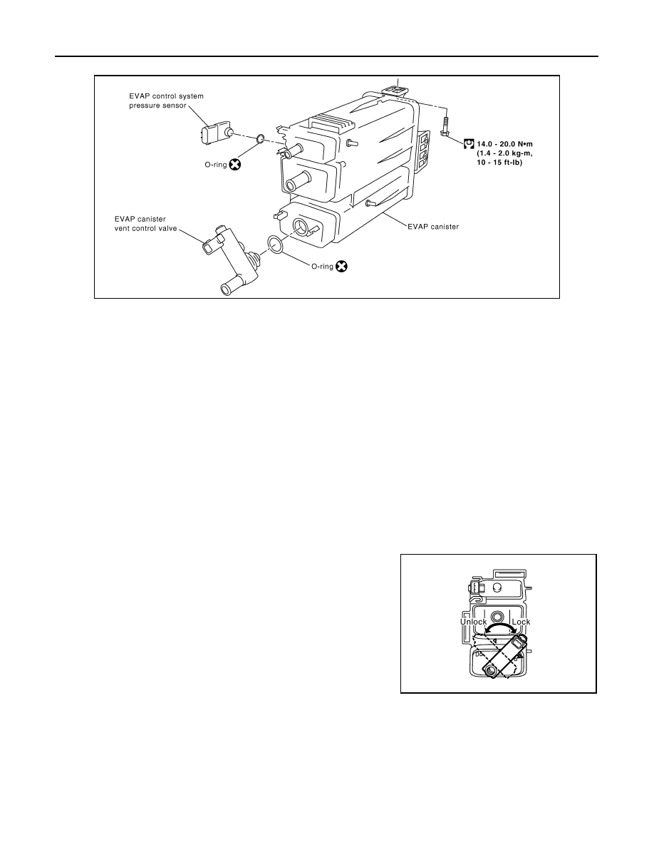
Exploded View
INFOID:0000000009720462
Removal and Installation
INFOID:0000000009720463
REMOVAL
1.
Lift up the vehicle.
2.
Remove EVAP canister fixing bolt.
3.
Remove EVAP canister.
NOTE:
The EVAP canister vent control valve and EVAP canister system pressure sensor can be removed without
removing the EVAP canister.
INSTALLATION
CAUTION:
Do not reuse O-rings.
Install in the reverse order of removal.
NOTE:
Tighten EVAP canister fixing bolt to the specified torque.
DISASSEMBLY
1.
Turn EVAP canister vent control valve counterclockwise.
2.
Remove the EVAP canister vent control valve.
ASSEMBLY
Assemble in the reverse order of disassembly.
CAUTION:
Always replace O-ring with a new one.
PBIB1383E
PBIB1384E