содержание .. 764 765 766 767 ..
Nissan Murano. Manual - part 766
FL-4
< PERIODIC MAINTENANCE >
FUEL SYSTEM
PERIODIC MAINTENANCE
FUEL SYSTEM
Inspection
INFOID:0000000009720453
Inspect fuel lines, fuel filler cap, and fuel tank for improper attach-
ment, leakage, cracks, damage, loose connections, chafing or dete-
rioration.
If necessary, repair or replace damaged parts.
Quick Connector
INFOID:0000000009720454
CAUTION:
• After connecting fuel tube quick connectors, check quick con-
nectors are secure.
• Ensure that connector and resin tube never contact any adja-
cent parts.
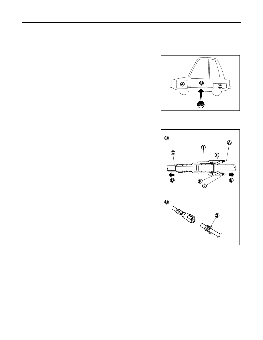
A
: Engine
B
: Fuel line
C
: Fuel tank
JPBIA0129ZZ
1
: Quick connector
2
: Retainer
A
: Hard tube (or the equivalent)
B
: Connection (cross-section)
C
: Resin tube
D
: To under floor fuel line
E
: To fuel tank
F
: Tab
G
: Disconnection
JPBIA0130ZZ