Nissan Murano. Manual - part 764


  Главная      Nissan     Nissan Murano (2014 year) - Service Manual


поиск по сайту            


содержание   ..  762  763  764  765   ..


Nissan Murano. Manual - part 764


FRONT DRIVE SHAFT

FAX-51

< REMOVAL AND INSTALLATION >

[AWD]

C

E

F

G

H

I

J

K

L

M

A

B

FAX

N

O

P

Left Side

1.

Fix drive shaft with a vise.

CAUTION:

Protect shaft using aluminum or copper plates when fixing with a vise.

2.

Disassemble boot (wheel side). Refer to 

FAX-49, "WHEEL SIDE : Disassembly and Assembly"

.

3.

Remove boot bands and boot (transaxle side).

Right Side

1.

Fix drive shaft with a vise.

CAUTION:

Protect shaft using aluminum or copper plates when fixing with a vise.

2.

Disassemble boot (wheel side). Refer to 

FAX-49, "WHEEL SIDE : Disassembly and Assembly"

.

3.

Remove dynamic damper, follow the procedure described below. 

a.

Remove damper bands.

b.

Remove dynamic damper from shaft.

4.

Remove boot bands and boot (transaxle side).

5.

Remove dust shield from housing assembly.

6.

Remove support bearing from link shaft, follow the procedure described below.

a.

Press out bearing housing and support bearing from link shaft.

b.

Remove dust shield from bearing housing.
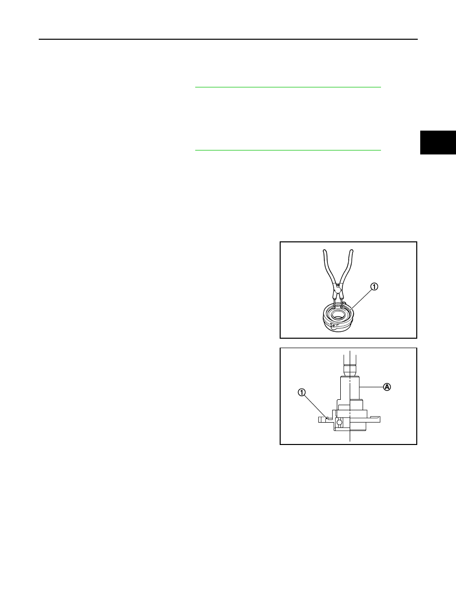
c.

Remove snap ring (1).

d.

Remove oil seal.

e.

Press out support bearing from bearing housing (1) with drift (A)
[SST: ST17130000 (

)]

ASSEMBLY

Left Side

1.

Install dust shield.

CAUTION:

Never reuse dust shield.

2.

Install circular clip.

CAUTION:

Never reuse circular clip.

3.

Clean old grease on housing assembly with paper waste.

JPDIF0177ZZ

JPDIF0192ZZ

FAX-52

< REMOVAL AND INSTALLATION >

[AWD]

FRONT DRIVE SHAFT

4.

Install boot securely into grooves (indicated by “*” marks) shown
in the figure.

CAUTION:

If grease adheres to the boot mounting surface (indicated
by “*” mark) on housing assembly, boot may be removed.
Remove all grease from the boot mounting surface.

5.

To prevent the deformation of the boot, adjust the boot installa-
tion length (L) to the specified value shown below by inserting
the suitable tool into the inside of boot from the large diameter
side of boot and discharging inside air.

CAUTION:

• If the boot installation length exceeds the standard, it may cause breakage of boot.
• Be careful not to touch the inside of the boot with the tip of tool.

6.

Install boot bands securely as shown in the figure.

a.

Put boot band in the groove on drive shaft boot. Then fit pawls
(

) into holes to temporary installation.

NOTE:
For the large diameter side, fit projection (A) and guide slit (B) at
first.

b.

Pinch projection on the band with suitable pliers to tighten band.

c.

Insert tip of band below end of the pawl.

7.

Secure housing assembly, and then make sure that they are in
the correct position when rotating boot. Reinstall them with boot
bands when the mounting positions become incorrect.

Right Side

1.

Install support bearing from link shaft, follow the procedure described below.

a.

Press support bearing to bearing housing (1) with drift (A) [SST:
ST35271000 (

)]

L

:  Refer  to 

FAX-55, "Drive Shaft"

.

JPDIF0144ZZ

JPDIF0157ZZ

JPDIF0158ZZ

JPDIF0192ZZ

FRONT DRIVE SHAFT

FAX-53

< REMOVAL AND INSTALLATION >

[AWD]

C

E

F

G

H

I

J

K

L

M

A

B

FAX

N

O

P

b.

Install snap ring (1).

CAUTION:

Never reuse snap ring.

c.

Install dust shield to baring housing.

CAUTION:

Never reuse dust shield.

d.

Install oil seal to bearing housing with drift.

CAUTION:

• Never reuse oil seal.
• Apply multi - purpose grease to oil seal lip.

e.

Press bearing housing assembly to link shaft.

f.

Install circular clip to link shaft.

CAUTION:

Never reuse circular clip.

2.

Clean old grease on housing assembly with paper waste.

3.

Install boot securely into grooves (indicated by “*” marks) shown
in the figure.

CAUTION:

If grease adheres to the boot mounting surface (indicated
by “*” mark) on housing assembly, boot may be removed.
Remove all grease from the boot mounting surface.

4.

To prevent the deformation of the boot, adjust the boot installa-
tion length (L) to the specified value shown below by inserting
the suitable tool into the inside of boot from the large diameter
side of boot and discharging inside air.

CAUTION:

• If the boot installation length exceeds the standard, it may cause breakage of boot.
• Be careful not to touch the inside of the boot with the tip of tool.

5.

Install boot bands securely as shown in the figure.

a.

Put boot band in the groove on drive shaft boot. Then fit pawls
(

) into holes to temporary installation.

NOTE:
For the large diameter side, fit projection (A) and guide slit (B) at
first.

b.

Pinch projection on the band with suitable pliers to tighten band.

c.

Insert tip of band below end of the pawl.

6.

Secure housing assembly, and then make sure that they are in
the correct position when rotating boot. Reinstall them with boot
bands when the mounting positions become incorrect.

7.

Assemble boot (wheel side) and joint sub-assembly. Refer to

FAX-49, "WHEEL SIDE : Disassembly and Assembly"

.

8.

Install dynamic damper, follow the procedure described below. 

a.

Install dynamic damper to shaft.

L

: Refer to 

FAX-54, "Inspection"

.

JPDIF0177ZZ

JPDIF0144ZZ

JPDIF0157ZZ

JPDIF0158ZZ

FAX-54

< REMOVAL AND INSTALLATION >

[AWD]

FRONT DRIVE SHAFT

b.

Secure dynamic damper with bands in the following specified
position (A) when installing.

CAUTION:

Never reuse bands.

Inspection

INFOID:0000000009717930

INSPECTION AFTER REMOVAL

• Move joint up/down, left/right, and in the axial directions. Check for motion that is not smooth and for signifi-

cant looseness.

• Check boot for cracks, damage, and leakage of grease.
• Disassemble drive shaft and exchange malfunctioning part if there

is a non-standard condition.

INSPECTION AFTER DISASSEMBLY

Shaft

Check shaft for runout, cracks, or other damage. Replace if necessary.

Dynamic Damper

Check damper for cracks or wear. Replace if necessary.

Joint Sub-Assembly (Wheel Side)

Check the following:
• Joint sub-assembly for rough rotation and excessive axial looseness.
• The inside of the joint sub-assembly for entry of foreign material.
• Joint sub-assembly for compression scars, cracks, and fractures inside of joint sub-assembly.
Replace joint sub-assembly if there are any non-standard conditions of components.

Housing Assembly (Transaxle Side)

Replace housing assembly if there is scratching or wear of housing assembly roller contact surface.

Link Shaft (Right side)

Check shaft for runout, cracks, or other damage. Replace if necessary.

Support Bearing (Right Side)

Make sure wheel bearing rolls freely and is free from noise, cracks, pitting or wear. Replace support bearing if
there are any non-standard conditions.

Support Bearing Bracket (Right Side)

Check for bending, cracks, or damage. Replace support bearing bracket if there are any non-standard condi-
tions.

: Refer to 

FAX-55, "Drive Shaft"

.

JPDIF0178ZZ

SDIA1190J


содержание   ..  762  763  764  765   ..