содержание .. 614 615 616 617 ..
Nissan Murano. Manual - part 616
EM-38
< REMOVAL AND INSTALLATION >
EXHAUST MANIFOLD AND THREE WAY CATALYST
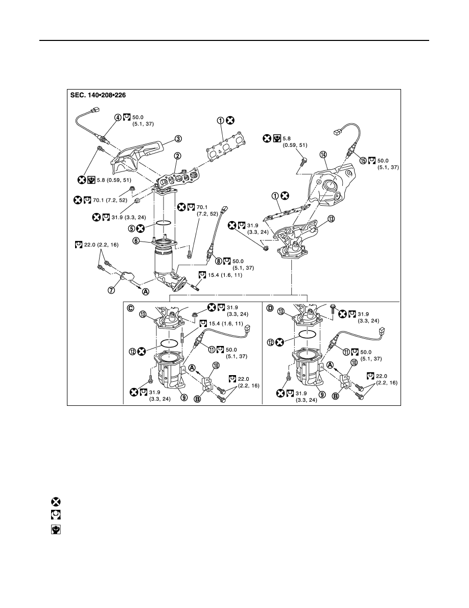
EXHAUST MANIFOLD AND THREE WAY CATALYST
Exploded View
INFOID:0000000009717971
Removal and Installation
INFOID:0000000009717972
REMOVAL
WARNING:
1.
Gasket
2.
Exhaust manifold (bank 1)
3.
Exhaust manifold cover (bank 1)
4.
Air fuel ratio sensor 1 (bank 1)
5.
Ring gasket
6.
Three way catalyst (bank 1)
7.
Three way catalyst support (bank 1)
8.
Heated oxygen sensor 2 (bank 1)
9.
Three way catalyst (bank 2)
10. Three way catalyst support (bank 2)
11. Heated oxygen sensor 2 (bank 2)
12.
Ring gasket
13. Exhaust manifold (bank 2)
14. Exhaust manifold cover (bank 2)
15.
Air fuel ratio sensor 1 (bank 2)
A.
To oil pan (upper)
B.
Upper mark
C.
Stud bolt and flange bolt type
(bank 2)
D.
Flange bolt type (bank 2)
: Always replace after every disassembly.
: N·m (kg-m, ft-lb)
: N·m (kg-m, in-lb)
JPBIA2710GB