Nissan Murano. Manual - part 617


  Главная      Nissan     Nissan Murano (2014 year) - Service Manual


поиск по сайту            


содержание   ..  615  616  617  618   ..


Nissan Murano. Manual - part 617


EM-42

< REMOVAL AND INSTALLATION >

EXHAUST MANIFOLD AND THREE WAY CATALYST

• Prevent rust preventives from adhering to the sensor body.

Inspection

INFOID:0000000009717973

INSPECTION AFTER REMOVAL
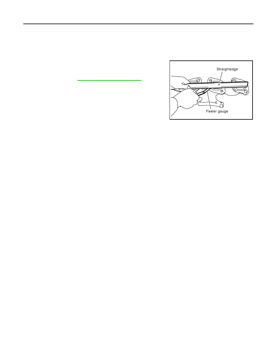
Surface Distortion

• Check the surface distortion of the exhaust manifold mating sur-

face with a straightedge and a feeler gauge.

• If it exceeds the limit, replace exhaust manifold.

Limit

: Refer to 

EM-147, "Exhaust Manifold"

.

PBIC1173E

OIL PAN AND OIL STRAINER

EM-43

< REMOVAL AND INSTALLATION >

C

D

E

F

G

H

I

J

K

L

M

A

EM

N

P

O

OIL PAN AND OIL STRAINER

Exploded View

INFOID:0000000009717974

Removal and Installation

INFOID:0000000009717975

REMOVAL

CAUTION:

To avoid the danger of being scalded, never drain engine oil when the engine is hot.
NOTE:
When removing oil pan (lower) or oil strainer only, take step 1 then step 19 and 20.

1.

Drain engine oil. Refer to 

LU-9, "Draining"

.

CAUTION:

Never spill engine oil on drive belt.

1.

Oil pan (upper)

2.

O-ring

3.

Oil pan gasket (front)

4.

Relief valve

5.

Oil pressure switch

6.

Oil cooler

7.

Connector bolt

8.

Oil filter

9.

Oil strainer

10. Drain plug

11.

Drain plug washer

12. Oil pan (lower)

13. Rear plate cover

14. Crankshaft position sensor (POS)

15. Oil pan gasket (rear)

A.

Comply with the assembly procedure 
when tightening. Refer to 

LU-11

B.

To oil pump

C.

Oil pan side

: Always replace after every disassembly.

: N·m (kg-m, ft-lb)

: N·m (kg-m, in-lb)

: Sealing point

JPBIA1636GB

EM-44

< REMOVAL AND INSTALLATION >

OIL PAN AND OIL STRAINER

2.

Drain engine coolant. Refer to 

CO-11, "Draining"

.

CAUTION:

Never spill engine coolant on drive belt.

3.

Remove following parts:
• Front road wheel and tires (RH and LH).
• Splash guard (RH and LH): Refer to 

EXT-26, "FENDER PROTECTOR : Exploded View"

.

• Exhaust front tube: Refer to 

EX-5, "Exploded View"

.

• Drive belt: Refer to 

EM-17, "Removal and Installation"

.

4.

Remove A/C compressor with piping connected, and temporarily secure it to aside. Refer to 

HA-37,

"Exploded View"

.

5.

Remove oil level gauge. Refer to 

EM-111, "Exploded View"

.

6.

Remove front drive shaft (RH). Refer to 

FAX-18, "Exploded View"

 (2WD models) or 

FAX-45, "Exploded

View"

 (AWD models).

7.

Remove three way catalyst (bank 1 and bank 2) from exhaust manifolds (bank 1 and bank 2). Refer to

EM-38, "Exploded View"

.

8.

Remove oil pressure switch.

9.

Remove oil filter. Refer to 

LU-11, "Removal and Installation"

.

10. Remove oil cooler and water pipes. Refer to 

LU-12, "Exploded View"

.

11. Support transaxle assembly with a suitable jack.

CAUTION:

When setting the transmission jack, be careful not to allow it to collide against the drain plug.

12. Support front suspension member with a suitable jack.

13. Remove engine mounting insulator (rear). Refer to 

EM-72, "2WD : Exploded View"

 (2WD models) or 

EM-

81, "AWD : Exploded View"

 (AWD models).

14. Remove engine mounting insulator (LH) mounting bolts from transaxle. Refer to 

EM-72, "2WD : Exploded

View"

 (2WD models) or 

EM-81, "AWD : Exploded View"

 (AWD models).

15. Remove rear torque rod through bolts from rear torque rod bracket. Refer to 

EM-72, "2WD : Exploded

View"

 (2WD models) or 

EM-81, "AWD : Exploded View"

 (AWD models).

16. Remove member stay, front suspension member fixing bolts and nuts. Refer to 

FSU-16, "Exploded View"

.

17. Lower the jack for the front suspension member to the height.
18. Remove transfer assembly. Refer to 

DLN-55, "Exploded View"

 (AWD models).

19. Remove oil pan (lower) as follows:

a.

Loosen mounting bolts in the reverse order as shown in the fig-
ure to remove.

b.

Insert the seal cutter [SST: KV10111100 (J-37228)] (A) between
oil pan (upper) and oil pan (lower).

CAUTION:

• Be careful not to damage the mating surfaces.
• Never insert a screwdriver, this will damage the mating

surfaces.

c.

Slide the seal cutter by tapping on the side of tool with a ham-
mer. Remove oil pan (lower).

PBIC0782E

JPBIA0276ZZ

OIL PAN AND OIL STRAINER

EM-45

< REMOVAL AND INSTALLATION >

C

D

E

F

G

H

I

J

K

L

M

A

EM

N

P

O

20. Remove oil strainer.

21. Loosen mounting bolts in the reverse order as shown in the fig-

ure to remove.
• Insert the seal cutter [SST: KV10111100 (J-37228)] between

oil pan (upper) and cylinder block. Slide seal cutter by tapping
on the side of tool with a hammer. Remove oil pan (upper).

CAUTION:

• Be careful not to damage the mating surfaces.
• Never insert a screwdriver, this will damage the mating

surfaces.

22. Remove O-rings (2) from bottom of cylinder block (1) and oil

pump (3).

23. Remove oil pan gaskets (1).

INSTALLATION

CAUTION:

Do not reuse O-rings or drain plug washer.
1.

Install oil pan (upper) as follows:

a.

Use a scraper to remove old liquid gasket from mating surfaces.

CAUTION:

Never scratch or damage the mating surfaces when clean-
ing off old liquid gasket.
• Also remove old liquid gasket from mating surface of cylinder

block.

• Remove old liquid gasket from the bolt holes and threads.

b.

Install new oil pan gaskets.

PBIC1636E

: Engine front

JPBIA1379ZZ

A

: Notch

B

:  Protrusion

: Engine front

JPBIA0433ZZ

MEM108A


содержание   ..  615  616  617  618   ..