Nissan Murano. Manual - part 60


  Главная      Nissan     Nissan Murano (2014 year) - Service Manual


поиск по сайту            


содержание   ..  58  59  60  61   ..


Nissan Murano. Manual - part 60


AV-18

< SYSTEM DESCRIPTION >

[BASE AUDIO WITHOUT COLOR DISPLAY]

DIAGNOSIS SYSTEM (AUDIO UNIT)

6.

Pressing the SEEK TRACK up switch displays the confirmation screen of “delete error record”. Press the
SEEK TRACK down switch if returning from RECORD DEL YES? to RECORD DEL NO?
The item is automatically determined approximately 6 seconds after it is displayed. Then the display
returns to AV TROUBLE DEL display item.

7.

Self-diagnosis mode is canceled when the ignition switch is turned OFF.
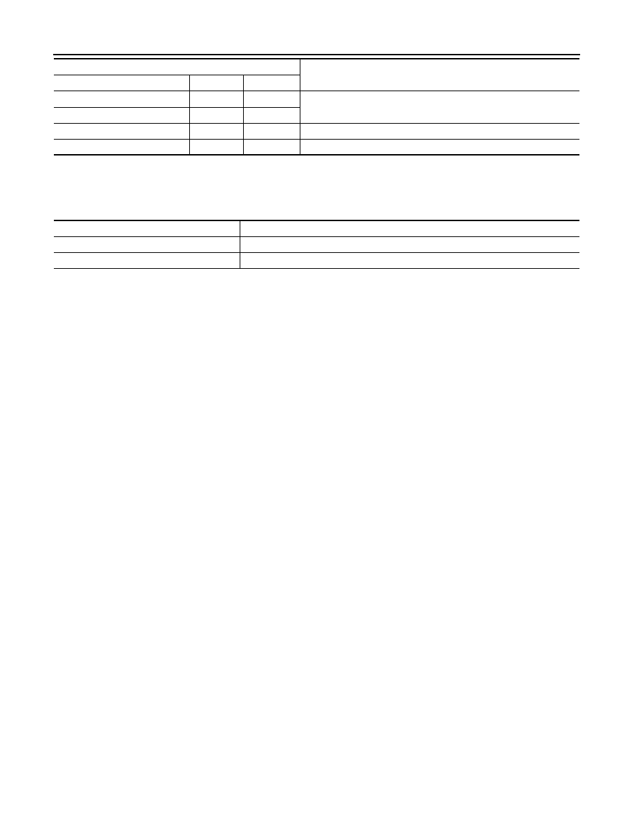
DISP

OK / UN

OK / 0 –39

The communication condition and error counter from the audio display 
unit to the audio unit.

DISP MPDT

OK / UN

OK / 0 –39

NO HISTORY BTHF

Not used.

AV TROUBLE DEL

The error record can be deleted.

Display item

Description

AV communication item

Current

Past

Display item

Description

RECORD DEL NO?

Does not delete error record.

RECORD DEL YES?

Deletes error record.

AV

POWER SUPPLY AND GROUND CIRCUIT

AV-19

< DTC/CIRCUIT DIAGNOSIS >

[BASE AUDIO WITHOUT COLOR DISPLAY]

C

D

E

F

G

H

I

J

K

L

M

B

A

O

P

DTC/CIRCUIT DIAGNOSIS

POWER SUPPLY AND GROUND CIRCUIT

AUDIO UNIT

AUDIO UNIT : Diagnosis Procedure

INFOID:0000000009721561

1.

CHECK FUSE

Check for blown fuses.

Is the inspection result normal?

YES

>> GO TO 2.

NO

>> Be sure to eliminate the cause of malfunction before installing new fuse. 

2.

CHECK POWER SUPPLY CIRCUIT

Check voltage between audio unit harness connectors and ground.

Is the inspection result normal?

YES

>> INSPECTION END

NO

>> Check harness between audio unit and fuse.

AUDIO DISPLAY UNIT

AUDIO DISPLAY UNIT : Diagnosis Procedure

INFOID:0000000009721562

1.

CHECK FUSE

Check for blown fuses.

Is the inspection result normal?

YES

>> GO TO 2.

NO

>> Be sure to eliminate the cause of malfunction before installing new fuse. 

2.

CHECK POWER SUPPLY CIRCUIT

Check voltage between audio display unit harness connectors and ground.

Is the inspection result normal?

YES

>> GO TO 3.

NO

>> Check harness between audio display unit and fuse.

3.

CHECK GROUND CIRCUIT

1.

Turn ignition switch OFF.

2.

Disconnect the harness connector audio display unit.

Power source

Fuse No.

Battery

35

Ignition switch ACC or ON

19

Signal name

Connector No.

Terminal No.

Ignition switch position

Value (Approx.)

Battery power supply

M46

19

OFF

Battery voltage

ACC power supply

7

ACC

Power source

Fuse No.

Battery

35

Ignition switch ACC or ON

19

Signal name

Connector No.

Terminal No.

Ignition switch position

Value (Approx.)

Battery power supply

M126

9

OFF

Battery voltage

ACC power supply

8

ACC

AV-20

< DTC/CIRCUIT DIAGNOSIS >

[BASE AUDIO WITHOUT COLOR DISPLAY]

POWER SUPPLY AND GROUND CIRCUIT

3.

Check continuity between audio display unit harness connector and ground.

Is the inspection result normal?

YES

>> INSPECTION END

NO

>> Repair harness or connector.

Signal name

Connector No.

Terminal No.

Ignition switch position

Continuity

Ground

M126

3

OFF

Existed

AV

AUDIO UNIT

AV-21

< ECU DIAGNOSIS INFORMATION >

[BASE AUDIO WITHOUT COLOR DISPLAY]

C

D

E

F

G

H

I

J

K

L

M

B

A

O

P

ECU DIAGNOSIS INFORMATION

AUDIO UNIT

Reference Values

INFOID:0000000009721563

TERMINAL LAYOUT

PHYSICAL VALUES

JSNIA1180ZZ

Terminal

(Wire color)

Description

Condition

Reference value

(Approx.)

+

Signal name

Input/

Output

2

(L)

3

(B)

Sound signal front LH

Output

Ignition 

switch 

ON

Sound output.

4

(LG)

5

(Y)

Sound signal rear LH

Output

Ignition 

switch 

ON

Sound output.

7

(R)

Ground

ACC power supply

Input

Ignition 

switch 

ACC

Battery voltage

SKIB3609E

SKIB3609E


содержание   ..  58  59  60  61   ..