содержание .. 57 58 59 60 ..
Nissan Murano. Manual - part 59
AV-14
< SYSTEM DESCRIPTION >
[BASE AUDIO WITHOUT COLOR DISPLAY]
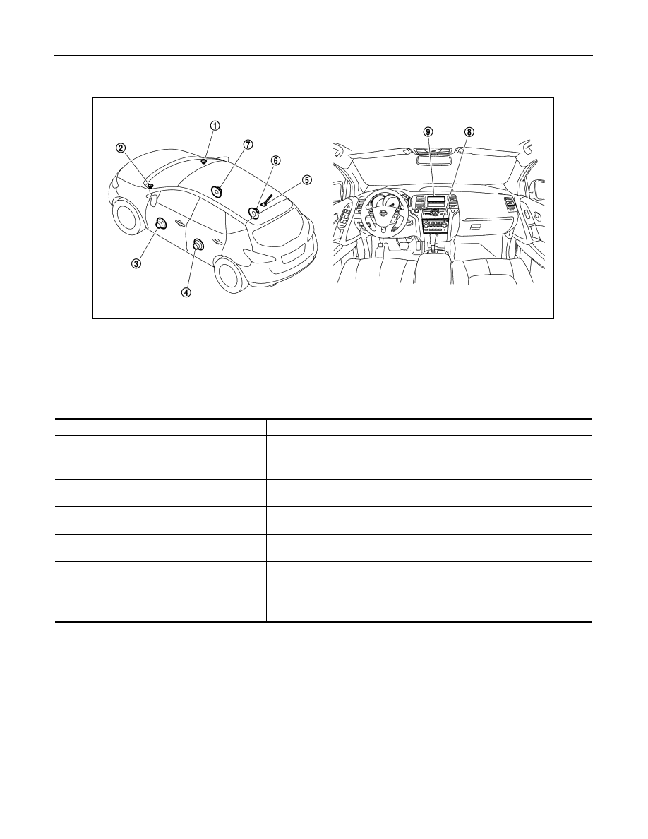
AUDIO SYSTEM
Component Parts Location
INFOID:0000000009721558
Component Description
INFOID:0000000009721559
1.
Front squawker RH
2.
Front squawker LH
3.
Front door speaker LH
4.
Rear door speaker LH
5.
Antenna base (antenna amp.)
6.
Rear door speaker RH
7.
Front door speaker RH
8.
Audio unit
9.
Audio display unit
JSNIA3510ZZ
Part name
Description
AUDIO UNIT
• Has radio function and CD playing function.
• Sound signals are output to each speaker.
AUDIO DISPLAY UNIT
Display images are controlled by AV communication from audio unit.
FRONT DOOR SPEAKER
• Outputs sound signals from audio unit.
• Outputs sound (mid and low range).
REAR DOOR SPEAKER
• Outputs sound signals from audio unit.
• Outputs sound (mid and low range).
FRONT SQUAWKER
• Outputs sound signals from audio unit.
• Outputs sound (high and mid range).
ANTENNA BASE
An antenna base integrated with radio antenna amp. is adopted.
ANTENNA AMP.
• Radio waves received by rod antenna are amplified and transmitted to audio
unit.
• Power (antenna amp. ON signal) is supplied from audio unit.