содержание .. 866 867 868 869 ..
Nissan X-Trail 32. Manual - part 868
P0075 INTAKE VALVE TIMING CONTROL
EC-601
< DTC/CIRCUIT DIAGNOSIS >
[QR25DE]
C
D
E
F
G
H
I
J
K
L
M
A
EC
N
P
O
2.
CHECK INTAKE VALVE TIMING CONTROL SOLENOID VALVE-II
1.
Remove intake valve timing control solenoid valve. Refer to
.
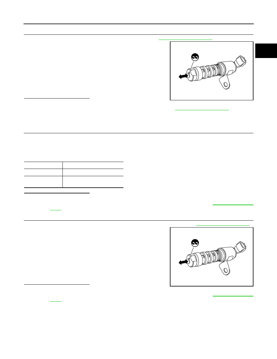
2.
Provide 12 V DC between intake valve timing control solenoid
valve terminals 1 and 2, and then interrupt it. Make sure that the
plunger moves as shown in the figure.
CAUTION:
Do not apply 12 V DC continuously for 5 seconds or more.
Doing so may result in damage to the coil in intake valve
timing control solenoid valve.
NOTE:
Always replace O-ring when intake valve timing control
solenoid valve is removed.
Is the inspection result normal?
YES
>> INSPECTION END
NO
>> Replace intake valve timing control solenoid valve. Refer to
Component Inspection (IVT Intermediate Lock Control Solenoid Valve)
INFOID:0000000010986318
1.
CHECK INTAKE VALVE TIMING INTERMEDIATE LOCK CONTROL SOLENOID VALVE-I
1.
Turn ignition switch OFF.
2.
Disconnect intake valve timing intermediate lock control solenoid valve harness connector.
3.
Check resistance between intake valve timing intermediate lock control solenoid valve terminals as fol-
lows.
Is the inspection result normal?
YES
>> GO TO 2.
NO
>> Replace intake valve timing intermediate lock control solenoid valve. Refer to
.
2.
CHECK INTAKE VALVE TIMING INTERMEDIATE LOCK CONTROL SOLENOID VALVE-II
1.
Remove intake valve timing intermediate lock control solenoid valve. Refer to
.
2.
Provide 12 V DC between intake valve timing intermediate lock
control solenoid valve terminals 1 and 2, and then interrupt it.
Make sure that the plunger moves as shown in the figure.
CAUTION:
Do not apply 12 V DC continuously for 5 seconds or more.
Doing so may result in damage to the coil in intake valve
timing intermediate lock control solenoid valve.
NOTE:
Always replace O-ring when intake valve timing intermedi-
ate lock control solenoid valve is removed.
Is the inspection result normal?
YES
>> INSPECTION END
NO
>> Replace intake valve timing intermediate lock control solenoid valve. Refer to
.
JMBIA2107ZZ
Terminals
Resistance
1 and 2
7.0 - 7.5
Ω
[at 20
°
C (68
°
F)]
1 or 2 and ground
∞
Ω
(Continuity should not exist)
JMBIA2107ZZ