содержание .. 864 865 866 867 ..
Nissan X-Trail 32. Manual - part 866
P0031, P0032 A/F SENSOR 1 HEATER
EC-593
< DTC/CIRCUIT DIAGNOSIS >
[QR25DE]
C
D
E
F
G
H
I
J
K
L
M
A
EC
N
P
O
Is the inspection result normal?
YES
>> GO TO 2.
NO
>> Repair or replace error-detected parts.
2.
CHECK A/F SENSOR 1 HEATER OUTPUT SIGNAL CIRCUIT
1.
Turn ignition switch OFF.
2.
Disconnect ECM harness connector.
3.
Check the continuity between A/F sensor 1 harness connector and ECM harness connector.
4.
Also check harness for short to ground and to power.
Is the inspection result normal?
YES
>> GO TO 3.
NO
>> Repair open circuit, short to ground or short to power in harness or connectors.
3.
CHECK A/F SENSOR 1 HEATER
Check the A/F sensor 1 heater. Refer to
EC-593, "Component Inspection"
.
Is the inspection result normal?
YES
>> GO TO 5.
NO
>> GO TO 4.
4.
REPLACE AIR FUEL RATIO (A/F) SENSOR 1
Replace malfunctioning air fuel ratio (A/F) sensor 1. Refer to
CAUTION:
• Discard any A/F sensor which has been dropped from a height of more than 0.5 m (19.7 in) onto a
hard surface such as a concrete floor; use a new one.
• Before installing new A/F sensor, clean exhaust system threads using Oxygen Sensor Thread
Cleaner [commercial service tool (J-43897-18 or J-43897-12)] and approved Anti-seize Lubricant
(commercial service tool).
>> INSPECTION END
5.
CHECK INTERMITTENT INCIDENT
GI-44, "Intermittent Incident"
.
>> INSPECTION END
Component Inspection
INFOID:0000000010986311
1.
CHECK AIR FUEL RATIO (A/F) SENSOR 1
1.
Turn ignition switch OFF.
2.
Disconnect A/F sensor 1 harness connector.
3.
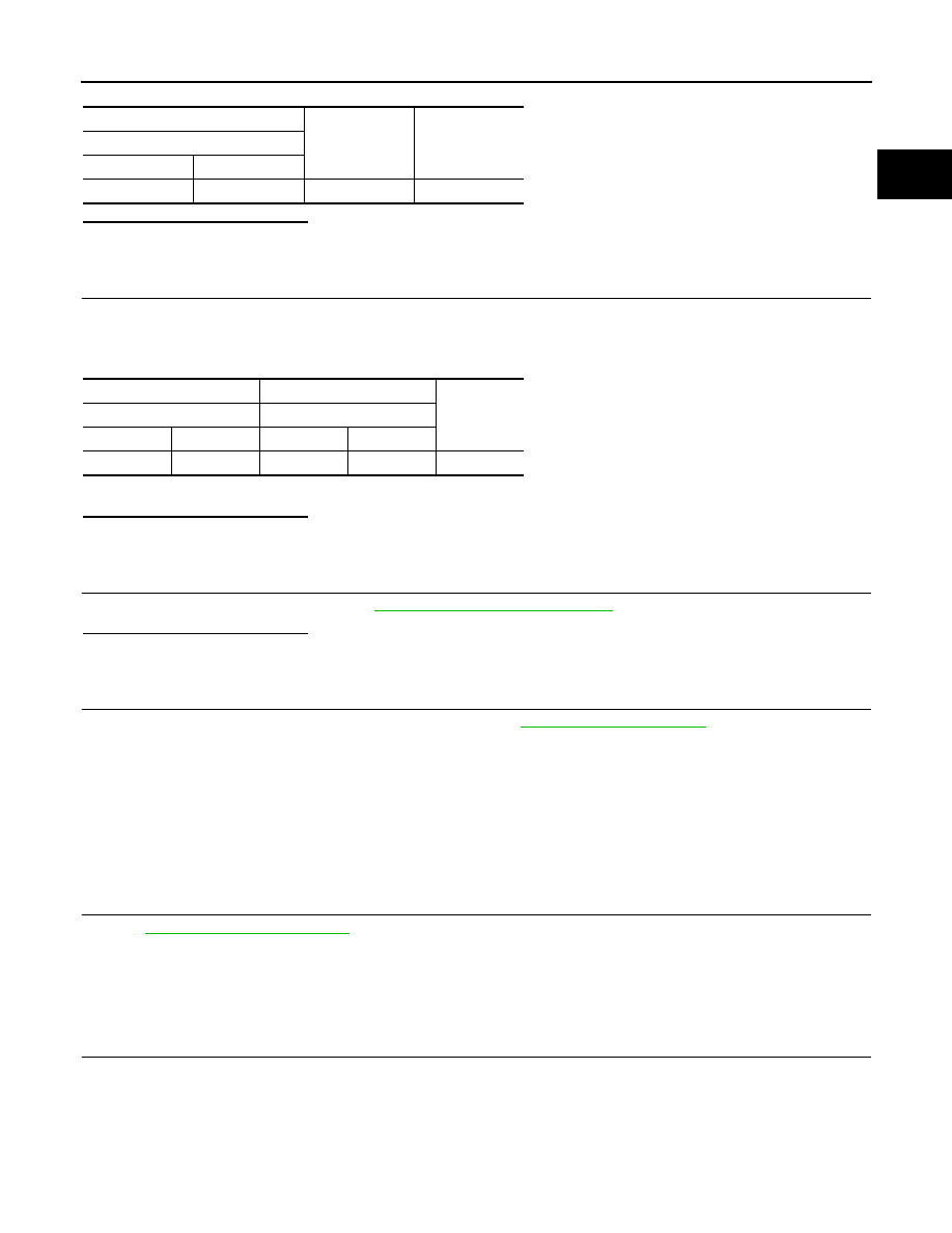
Check resistance between A/F sensor 1 terminals as per the following.
+
−
Voltage
A/F sensor 1
Connector
Terminal
F27
4
Ground
Battery voltage
+
−
Continuity
A/F sensor 1
ECM
Connector
Terminal
Connector
Terminal
F27
3
F68
53
Existed