Nissan X-Trail 32. Manual - part 865


  Главная      Nissan     Nissan X-Trail 32 - Service Manual


поиск по сайту            


содержание   ..  863  864  865  866   ..


Nissan X-Trail 32. Manual - part 865


P0014 EVT CONTROL

EC-589

< DTC/CIRCUIT DIAGNOSIS >

[QR25DE]

C

D

E

F

G

H

I

J

K

L

M

A

EC

N

P

O

Follow the procedure “With CONSULT” above.

Is 1st trip DTC detected?

YES

>> Proceed to 

EC-589, "Diagnosis Procedure"

NO

>> GO TO 4.

4.

PERFORM DTC CONFIRMATION PROCEDURE-2

With CONSULT

1.

Select “DATA MONITOR” mode of “ENGINE” using CONSULT.

2.

Maintain the following conditions for at least 20 consecutive seconds.

CAUTION:

Always drive at a safe speed.

3.

Check 1st trip DTC.

With GST

Follow the procedure “With CONSULT” above.

Is 1st trip DTC detected?

YES

>> Proceed to 

EC-589, "Diagnosis Procedure"

NO

>> INSPECTION END

Diagnosis Procedure

INFOID:0000000010986307

1.

CHECK DTC PRIORITY

If DTC P0014 is displayed with DTC P0078 or P1078, first perform the trouble diagnosis for DTC P0078 or
P1078.

Is applicable DTC detected?

YES

>> Perform diagnosis of applicable. Refer to 

EC-517, "DTC Index"

.

NO

>> GO TO 2.

2.

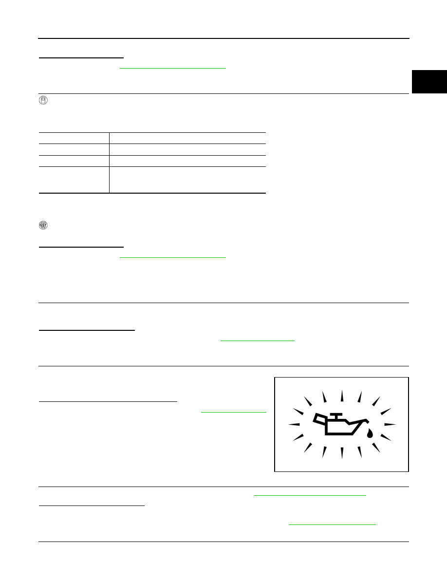
CHECK OIL PRESSURE WARNING LAMP

1.

Start engine.

2.

Check oil pressure warning lamp and confirm it is not illumi-
nated.

Is oil pressure warning lamp illuminated?

YES

>> Check the engine oil level. Refer to 

LU-25, "Inspection"

.

NO

>> GO TO 3.

3.

CHECK EXHAUST VALVE TIMING CONTROL SOLENOID VALVE

Check the exhaust valve timing control solenoid valve. Refer to 

EC-586, "Component Inspection"

.

Is the inspection result normal?

YES

>> GO TO 4.

NO

>> Replace exhaust valve timing control solenoid valve. Refer to 

EM-210, "Exploded View"

.

4.

CHECK CRANKSHAFT POSITION SENSOR (POS)

ENG SPEED

1,700 - 2,950 rpm (A constant rotation is maintained.)

COOLAN TEMP/S

More than 70

°

C (158

°

F)

Selector lever

D position

Driving location uphill

Driving vehicle uphill
(Increased engine load will help maintain the driving 
conditions required for this test.)

PBIA8559J

EC-590

< DTC/CIRCUIT DIAGNOSIS >

[QR25DE]

P0014 EVT CONTROL

Check the crankshaft position sensor (POS). Refer to 

EC-678, "Component Inspection (Crankshaft Position

sensor)"

.

Is the inspection result normal?

YES

>> GO TO 5.

NO

>> Replace crankshaft position sensor (POS). Refer to 

EM-247, "Exploded View"

.

5.

CHECK EXHAUST VALVE TIMING CONTROL POSITION SENSOR

Check the exhaust valve timing control position sensor. Refer to 

EC-715, "Component Inspection"

.

Is the inspection result normal?

YES

>> GO TO 6.

NO

>> Replace exhaust valve timing control position sensor. Refer to 

EM-221, "Exploded View"

.

6.

CHECK CAMSHAFT (EXH)

Check the following.
• Accumulation of debris to the signal plate of camshaft rear end
• Chipping signal plate of camshaft rear end
Is the inspection result normal?

YES

>> GO TO 7.

NO

>> Remove debris and clean the signal plate of camshaft

rear end or replace camshaft. Refer to 

EM-222,

"Removal and Installation"

.

7.

CHECK TIMING CHAIN INSTALLATION

Check service records for any recent repairs that may cause timing chain misaligned.

Are there any service records that may cause timing chain misaligned?

YES

>> Check timing chain installation. Refer to 

EM-211, "Removal and Installation"

.

NO

>> GO TO 8.

8.

CHECK LUBRICATION CIRCUIT

Refer to 

LU-25, "Inspection"

.

Is the inspection result normal?

YES

>> GO TO 9.

NO

>> Clean lubrication line.

9.

CHECK INTERMITTENT INCIDENT

Refer to 

GI-44, "Intermittent Incident"

.

>> INSPECTION END

Component Inspection

INFOID:0000000010986308

1.

CHECK EXHAUST VALVE TIMING CONTROL SOLENOID VALVE-1

1.

Turn ignition switch OFF.

2.

Disconnect exhaust valve timing control solenoid valve harness connector.

3.

Check resistance between exhaust valve timing control solenoid valve terminals as per the following.

JPBIA5856ZZ

Exhaust valve timing control solenoid valve

Resistance

+

Terminal

1

 2

7.0 - 7.7 

 [at 20

°

C (68

°

F)]

P0014 EVT CONTROL

EC-591

< DTC/CIRCUIT DIAGNOSIS >

[QR25DE]

C

D

E

F

G

H

I

J

K

L

M

A

EC

N

P

O

Is the inspection result normal?

YES

>> GO TO 2.

NO

>> Replace exhaust valve timing control solenoid valve. Refer to 

EM-210, "Exploded View"

.

2.

CHECK EXHAUST VALVE TIMING CONTROL SOLENOID VALVE-2

1.

Remove exhaust valve timing control solenoid valve. Refer to 

EM-210, "Exploded View"

.

2.

Provide 12 V DC between exhaust valve timing control solenoid
valve terminals 1 and 2, and then interrupt it. Check that the
plunger moves as shown in the figure.

CAUTION:

Do not apply 12 V DC continuously for 5 seconds or more.
Doing so may result in damage to the coil in exhaust valve
timing control solenoid valve.
NOTE:
Always replace O-ring when exhaust valve timing control
solenoid valve is removed.

Is the inspection result normal?

YES

>> INSPECTION END

NO

>> Replace exhaust valve timing control solenoid valve. Refer to 

EM-210, "Exploded View"

.

1

Ground


(Continuity should not exist)

2

Exhaust valve timing control solenoid valve

Resistance

+

Terminal

JMBIA0079ZZ

EC-592

< DTC/CIRCUIT DIAGNOSIS >

[QR25DE]

P0031, P0032 A/F SENSOR 1 HEATER

P0031, P0032 A/F SENSOR 1 HEATER

DTC Description

INFOID:0000000010986309

DTC DETECTION LOGIC

POSSIBLE CAUSE

DTC P0031

• Harness or connectors (A/F sensor 1 heater circuit is open or shorted.)
• A/F sensor 1 heater

DTC P0032

• Harness or connectors (A/F sensor 1 heater circuit is shorted.)
• A/F sensor 1 heater

FAIL-SAFE

Not applicable

DTC CONFIRMATION PROCEDURE

1.

PRECONDITIONING

If DTC Confirmation Procedure has been previously conducted, always perform the following procedure
before conducting the next test.
1.

Turn ignition switch OFF and wait at least 10 seconds.

2.

Turn ignition switch ON.

3.

Turn ignition switch OFF and wait at least 10 seconds.

TESTING CONDITION:
Before performing the following procedure, confirm that battery voltage is more than between 11 V at
idle.

>> GO TO 2.

2.

PERFORM DTC CONFIRMATION PROCEDURE

1.

Start engine and let it idle for at least 10 seconds.

2.

Check 1st trip DTC.

Is 1st trip DTC detected?

YES

>> Proceed to 

EC-592, "Diagnosis Procedure"

.

NO

>> INSPECTION END

Diagnosis Procedure

INFOID:0000000010986310

1.

CHECK AIR FUEL RATIO (A/F) SENSOR 1 POWER SUPPLY CIRCUIT

1.

Disconnect air fuel ratio (A/F) sensor 1 harness connector.

2.

Turn ignition switch ON.

3.

Check the voltage between A/F sensor 1 harness connector and ground.

DTC No.

CONSULT screen terms

(Trouble diagnosis content)

DTC detecting condition

P0031

A/F SEN1 HTR (B1)
[Air fuel ratio (A/F) sensor 1 heater (bank 
1)control circuit low]

The current amperage in the A/F sensor 1 heater circuit is out of the normal 
range.
(An excessively low voltage signal is sent to ECM through the A/F sensor 
1 heater.)

P0032

A/F SEN1 HTR (B1)
[Air fuel ratio (A/F) sensor 1 heater (bank 
1)control circuit high]

The current amperage in the A/F sensor 1 heater circuit is out of the normal 
range.
(An excessively high voltage signal is sent to ECM through the A/F sensor 
1 heater.)


содержание   ..  863  864  865  866   ..