Nissan X-Trail 32. Manual - part 867


  Главная      Nissan     Nissan X-Trail 32 - Service Manual


поиск по сайту            


содержание   ..  865  866  867  868   ..


Nissan X-Trail 32. Manual - part 867


P0037, P0038 HO2S2 HEATER

EC-597

< DTC/CIRCUIT DIAGNOSIS >

[QR25DE]

C

D

E

F

G

H

I

J

K

L

M

A

EC

N

P

O

Is the inspection result normal?

YES

>> INSPECTION END

NO

>> GO TO 2.

2.

REPLACE HEATED OXYGEN SENSOR 2

Replace heated oxygen sensor 2. Refer to 

EX-12, "Exploded View"

.

CAUTION:

• Discard any sensor which has been dropped from a height of more than 0.5 m (19.7 in) onto a hard

surface such as a concrete floor; use a new one.

• Before installing new sensor, clean exhaust system threads using Oxygen Sensor Thread Cleaner

[commercial service tool (J-43897-18 or J43897-12)] and approved Anti-seize Lubricant (commercial
service tool).

>> INSPECTION END

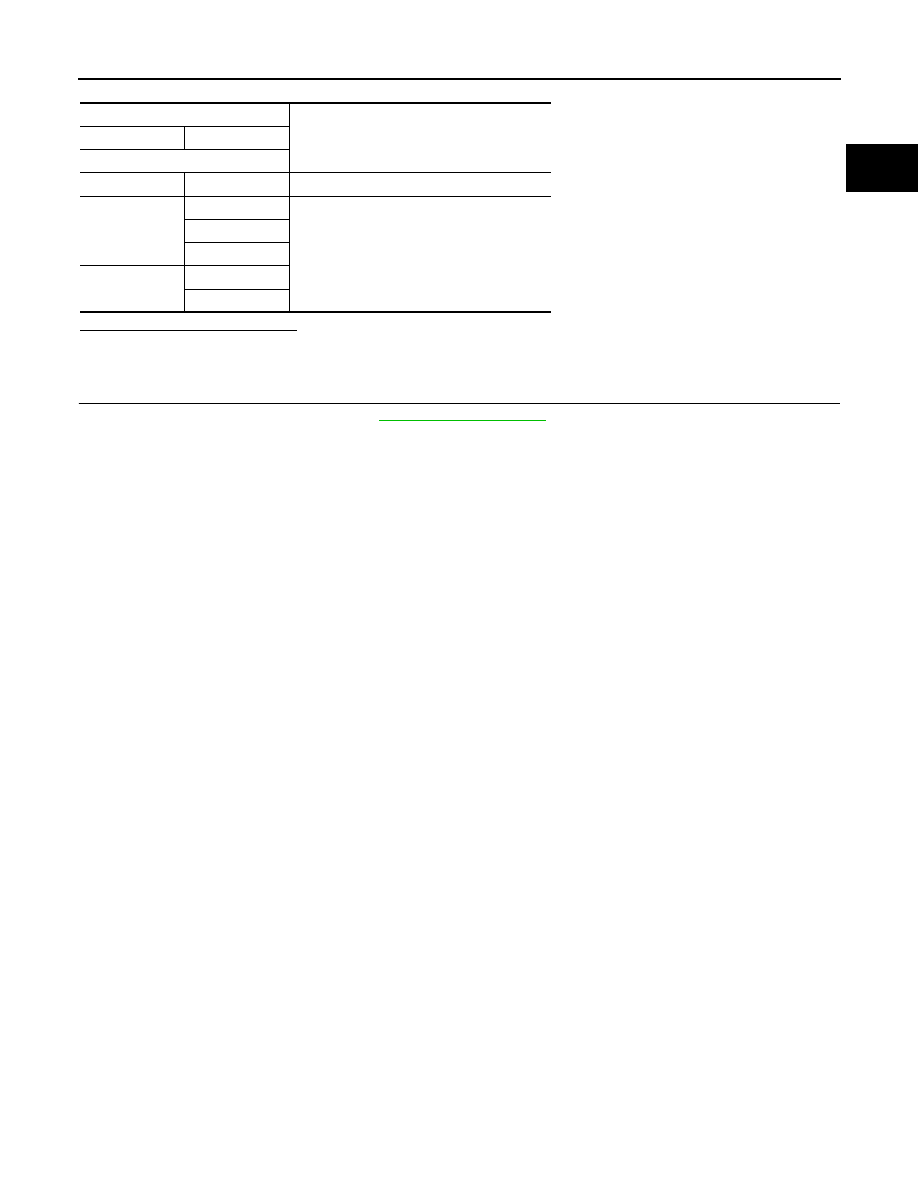
Heated oxygen sensor 2

Resistance

+

Terminal

4

3

3.3 - 4.4 

 [at 25

°

C (77

°

F)]

1

2


(Continuity should not exist)

3

4

2

3

4

EC-598

< DTC/CIRCUIT DIAGNOSIS >

[QR25DE]

P0075 INTAKE VALVE TIMING CONTROL

P0075 INTAKE VALVE TIMING CONTROL

DTC Description

INFOID:0000000010986315

DTC DETECTION LOGIC

POSSIBLE CAUSE

• Harness or connectors
- Intake valve timing control solenoid valve circuit is open or shorted.
- Intake valve timing intermediate lock control solenoid valve circuit is open or shorted.
• Intake valve timing control solenoid valve
• Intake valve timing intermediate lock control solenoid valve

FAIL-SAFE

Not applicable

DTC CONFIRMATION PROCEDURE

1.

PRECONDITIONING

If DTC Confirmation Procedure has been previously conducted, always perform the following procedure
before conducting the next test.
1.

Turn ignition switch OFF and wait at least 10 seconds.

2.

Turn ignition switch ON.

3.

Turn ignition switch OFF and wait at least 10 seconds.

>> GO TO 2.

2.

PERFORM DTC CONFIRMATION PROCEDURE

1.

Start engine and let it idle for 5 seconds.

2.

Check 1st trip DTC.

Is 1st trip DTC detected?

YES

>> Proceed to 

EC-598, "Diagnosis Procedure"

.

NO

>> INSPECTION END

Diagnosis Procedure

INFOID:0000000010986316

1.

CHECK INTAKE VALVE TIMING (IVT) CONTROL SOLENOID VALVE POWER SUPPLY

1.

Turn ignition switch OFF.

2.

Disconnect IVT control solenoid valve harness connector.

3.

Turn ignition switch ON.

4.

Check the voltage between intake valve timing control solenoid valve harness connector and ground.

Is the inspection result normal?

YES

>> GO TO 3.

NO

>> GO TO 2.

2.

CHECK IVT CONTROL SOLENOID VALVE POWER SUPPLY CIRCUIT

DTC No.

CONSULT screen terms

(Trouble diagnosis content)

DTC detecting condition

P0075

INT/V TIM V/CIR-B1
(Intake valve control solenoid circuit bank 1)

• ECM detects an abnormal voltage in the intake valve timing control sole-

noid valve control circuit.

• ECM detects an abnormal voltage in the intake valve timing intermediate 

lock control solenoid valve control circuit.

+

Voltage

IVT control solenoid valve

Connector

Terminal

F108

1

Ground

Battery voltage

P0075 INTAKE VALVE TIMING CONTROL

EC-599

< DTC/CIRCUIT DIAGNOSIS >

[QR25DE]

C

D

E

F

G

H

I

J

K

L

M

A

EC

N

P

O

1.

Turn ignition switch OFF.

2.

Disconnect IPDM E/R harness connector.

3.

Check the continuity between IVT control solenoid valve harness connector and IPDM E/R harness con-
nector.

4.

Also check harness for short to ground.

Is the inspection result normal?

YES

>> Perform the trouble diagnosis for power supply circuit.

NO

>> Repair or replace error-detected parts.

3.

CHECK IVT CONTROL SOLENOID VALVE GROUND CIRCUIT

1.

Turn ignition switch OFF.

2.

Disconnect ECM harness connector.

3.

Check the continuity between IVT control solenoid valve harness connector and ECM harness connector.

4.

Also check harness for short to ground and short to power. 

Is the inspection result normal?

YES

>> GO TO 4.

NO

>> Repair or replace error-detected parts.

4.

CHECK IVT CONTROL SOLENOID VALVE

Check the IVT control solenoid valve. Refer to 

EC-600, "Component Inspection (IVT Control Solenoid Valve)"

.

Is the inspection result normal?

YES

>> GO TO 5.

NO

>> Replace IVT control solenoid valve. Refer to 

EM-210, "Exploded View"

.

5.

CHECK IVT INTERMEDIATE LOCK CONTROL SOLENOID VALVE POWER SUPPLY

1.

Disconnect IVT intermediate lock control solenoid valve harness connector.

2.

Turn ignition switch ON.

3.

Check the voltage between IVT intermediate lock control solenoid valve harness connector and ground.

Is the inspection result normal?

YES

>> GO TO 7.

NO

>> GO TO 6.

6.

CHECK IVT INTERMEDIATE LOCK CONTROL SOLENOID VALVE POWER SUPPLY CIRCUIT

1.

Turn ignition switch OFF.

2.

Disconnect IPDM E/R harness connector.

3.

Check the continuity between IVT intermediate lock control solenoid valve harness connector and IPDM
E/R harness connector.

+

Continuity

IVT control solenoid valve

IPDM E/R

Connector

Terminal

Connector

Terminal

F108

1

F72

78

Existed

+

Continuity

IVT control solenoid valve

ECM

Connector

Terminal

Connector

Terminal

F108

2

F68

93

Existed

+

Voltage

IVT intermediate lock control 

solenoid valve

Connector

Terminal

F111

1

Ground

Battery voltage

EC-600

< DTC/CIRCUIT DIAGNOSIS >

[QR25DE]

P0075 INTAKE VALVE TIMING CONTROL

4.

Also check harness for short to ground.

Is the inspection result normal?

YES

>> Perform the trouble diagnosis for power supply circuit.

NO

>> Repair or replace error-detected parts.

7.

CHECK IVT INTERMEDIATE LOCK CONTROL SOLENOID VALVE GROUND CIRCUIT

1.

Turn ignition switch OFF.

2.

Disconnect ECM harness connector.

3.

Check the continuity between IVT intermediate lock control solenoid valve harness connector and ECM
harness connector.

4.

Also check harness for short to ground and short to power. 

Is the inspection result normal?

YES

>> GO TO 8.

NO

>> Repair or replace error-detected parts.

8.

CHECK IVT INTERMEDIATE LOCK CONTROL SOLENOID VALVE

Check the IVT intermediate lock control solenoid valve. Refer to 

EC-601, "Component Inspection (IVT Inter-

mediate Lock Control Solenoid Valve)"

.

Is the inspection result normal?

YES

>> GO TO 9.

NO

>> Replace IVT intermediate lock control solenoid valve. Refer to 

EM-210, "Exploded View"

.

9.

CHECK INTERMITTENT INCIDENT

Refer to 

GI-44, "Intermittent Incident"

.

>> INSPECTION END

Component Inspection (IVT Control Solenoid Valve)

INFOID:0000000010986317

1.

CHECK INTAKE VALVE TIMING CONTROL SOLENOID VALVE-I

1.

Turn ignition switch OFF.

2.

Disconnect intake valve timing control solenoid valve harness connector.

3.

Check resistance between intake valve timing control solenoid valve terminals as follows.

Is the inspection result normal?

YES

>> GO TO 2.

NO

>> Replace intake valve timing control solenoid valve. Refer to 

EM-210, "Exploded View"

.

+

Continuity

IVT intermediate lock con-

trol solenoid valve

IPDM E/R

Connector

Terminal

Connector

Terminal

F111

1

F72

78

Existed

+

Continuity

IVT intermediate lock con-

trol solenoid valve

ECM

Connector

Terminal

Connector

Terminal

F111

2

F68

56

Existed

Terminals

Resistance

1 and 2

7.0 - 7.5 

 [at 20

°

C (68

°

F)]

1 or 2 and ground


(Continuity should not exist)


содержание   ..  865  866  867  868   ..