Nissan X-Trail 32. Manual - part 733


  Главная      Nissan     Nissan X-Trail 32 - Service Manual


поиск по сайту            


содержание   ..  731  732  733  734   ..


Nissan X-Trail 32. Manual - part 733


SYSTEM

EC-61

< SYSTEM DESCRIPTION >

[MR20DD]

C

D

E

F

G

H

I

J

K

L

M

A

EC

N

P

O

Cam Position Detection

The camshaft position sensor mounted at the rear of the cylinder head detects a cam position, by using the-
groove on the plate located at the rear of the exhaust camshaft.

Feedback Control

The camshaft position sensor feeds back an actual cam position signal to ECM. Based on the signal, ECM
controls the exhaust valve timing control solenoid valve to satisfy the optimum target valve opening/closing
timing according to a driving condition.

INTAKE MANIFOLD RUNNER CONTROL

INTAKE MANIFOLD RUNNER CONTROL : System Description

INFOID:0000000010775044
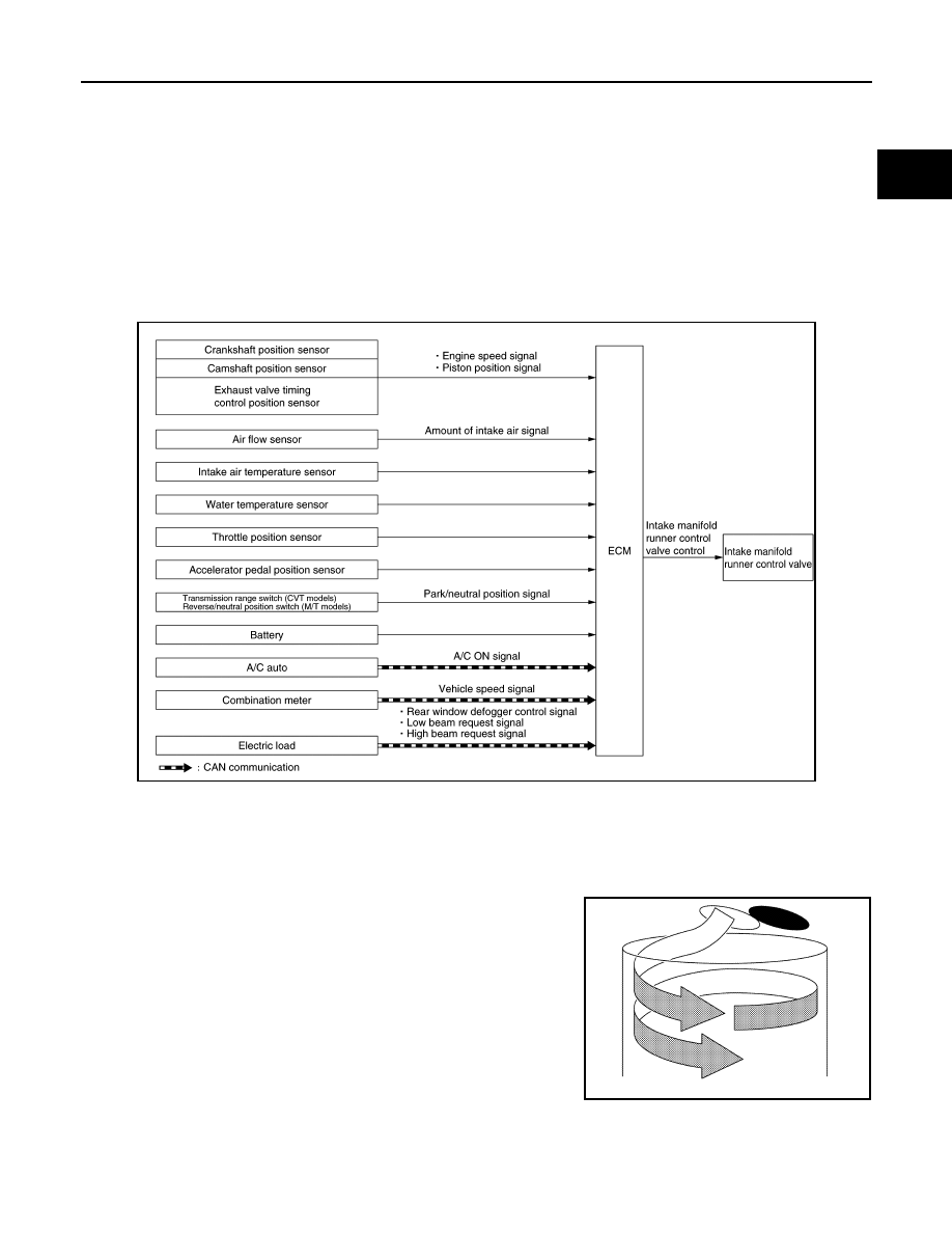
System Diagram

SYSTEM DESCRIPTION

The intake manifold runner control valve installed at intake manifold generates swirl flow (revolving flow) in
combustion chamber, and by that effect air-fuel mixture is homogenized so that stabilizes combustion. The
intake manifold runner control valve is driven by DC motor and controlled by ECM.

IDLING, LOW SPEED·SMALL LOAD RANGE

With intake manifold runner control valve closed the flowing field of
swirl flow (revolving flow) is generated by increased flow speed of
gas and improves combustion so that enables stable combustion.

MIDDLE·HIGH SPEED RANGE

JSBIA5013GB

JSBIA1215JP

EC-62

< SYSTEM DESCRIPTION >

[MR20DD]

SYSTEM

• With intake manifold runner control valve opened the flowing field

mainly consist of tumble (vertical revolving flow) by atomizer, port
shape and shallow piston head is generated.

• Which makes more swirl remained at the latter half of compression

process so that improves combustion and enables stable combus-
tion.

OPERATION OF INTAKE MANIFOLD RUNNER CONTROL VALVE

When the engine is idling or running at slow speed the vales are closed and swirl flow is generated. By closing
valves the flowing speed of gas is increased and it stabilizes combustion also improves fuel efficiency. 

ENGINE PROTECTION CONTROL AT LOW ENGINE OIL PRESSURE

ENGINE PROTECTION CONTROL AT LOW ENGINE OIL PRESSURE : System De-
scription

INFOID:0000000010775045

System Diagram

SYSTEM DESCRIPTION

• The engine protection control at low engine oil pressure warns the driver of a decrease in engine oil pres-

sure by the engine oil pressure warning lamp before the engine becomes damaged.

• When detecting a decrease in engine oil pressure at an engine speed less than 1,000 rpm, ECM transmits

an engine oil pressure warning lamp signal to the combination meter.The combination meter turns ON the
engine oil pressure warning lamp, according to the signal.

• When detecting a decrease in engine oil pressure at an engine speed 1,000 rpm or more, ECM transmits an

engine oil pressure warning lamp signal to the combination meter. When detecting a decrease in engine oil
pressure, ECM cuts fuel if the engine speed exceeds the specified value. Refer to 

EC-103, "Fail-safe"

.

JSBIA1214JP

Valve position

operating condition

Valve closed

Idling, low ·small load range

Valve opened

Other than above

JSBIA1212JP

JSBIA1213JP

JSBIA4201GB

SYSTEM

EC-63

< SYSTEM DESCRIPTION >

[MR20DD]

C

D

E

F

G

H

I

J

K

L

M

A

EC

N

P

O

*: When detecting a normal engine oil pressure, ECM turns OFF the engine oil pressure warning lamp.

AIR CONDITIONING CUT CONTROL

AIR CONDITIONING CUT CONTROL : System Description

INFOID:0000000010775046

System Diagram

SYSTEM DESCRIPTION

This system improves engine operation when the air conditioner is used.
Under the following conditions, the air compressor is turned off.
• When the accelerator pedal is fully depressed (selector lever is in R position).
• When cranking the engine.
• At high engine speeds.
• When the engine coolant temperature becomes excessively high.
• When operating power steering during low engine speed or low vehicle speed.
• When engine speed is excessively low.
• When refrigerant pressure is excessively low or high.

AUTOMATIC SPEED CONTROL DEVICE (ASCD)

Decrease in engine oil 

pressure

Engine speed

Combination meter

Fuel cut

Engine oil pressure warning lamp

Detection

Less than 1,000 rpm

ON

*

NO

1,000 rpm or more

ON

YES

JSBIA5011GB

EC-64

< SYSTEM DESCRIPTION >

[MR20DD]

SYSTEM

AUTOMATIC SPEED CONTROL DEVICE (ASCD) : System Description

INFOID:0000000010775047

System Diagram

BASIC ASCD SYSTEM

CAUTION:

Always drive vehicle in safe manner according to traffic conditions and obey all traffic laws.
• Automatic Speed Control Device (ASCD) allows a driver to keep vehicle at predetermined constant speed

without depressing accelerator pedal by driver

s setting of vehicle speed

*

.

*: Driver can set the vehicle speed between approximately 40 km/h (25 MPH) and 172 km/h [107 MPH (for
CVT)] or 181 km/h [112 MPH (for M/T)].

• ECM transmits a ASCD operation status signal to the combination meter and operation status of ASCD is

indicated on the information display in the combination meter. Refer to 

EC-70, "AUTOMATIC SPEED CON-

TROL DEVICE (ASCD) : Switch Name and Function"

.

• If any malfunction occurs in ASCD system, it automatically deactivates control.

CANCEL OPERATION

• When any of following conditions exist, cruise operation will be canceled.
- MAIN switch is pressed (Set speed will be cleared)
- CANCEL switch is pressed
- More than 2 switches at ASCD steering switch are pressed at the same time (Set speed will be cleared)
- Brake pedal is depressed
- Selector lever is in N, P or R range
- Vehicle speed decreased to 13 km/h (8 MPH) lower than the set speed
- VDC system is operated
- Actual vehicle speed decreased to approximately 30 km/h (18 MPH) or less
• When the ECM detects any of the following conditions, the ECM will cancel the cruise operation and inform

the driver by blinking ASCD indicator.

- Engine coolant temperature is excessively higher than the normal operating temperature, ASCD indicator

may blink slowly.
(When the engine coolant temperature decreases to the normal operating temperature, ASCD indicator will
stop blinking and the cruise operation will be able to work by pressing SET/COAST switch or RESUME/
ACCELERATE switch.)

- Malfunction for some self-diagnoses regarding ASCD control

(When ASCD is operating, all of ASCD operations will be canceled and vehicle speed memory will be
erased.)

ECO MODE SYSTEM

JSBIA5012GB


содержание   ..  731  732  733  734   ..