Nissan X-Trail 32. Manual - part 731


  Главная      Nissan     Nissan X-Trail 32 - Service Manual


поиск по сайту            


содержание   ..  729  730  731  732   ..


Nissan X-Trail 32. Manual - part 731


SYSTEM

EC-53

< SYSTEM DESCRIPTION >

[MR20DD]

C

D

E

F

G

H

I

J

K

L

M

A

EC

N

P

O

The mixture ratio feedback system provides the best air-fuel mixture ratio for driveability and emission control.
The three way catalyst (manifold) can better reduce CO, HC and NOx emissions. This system uses A/F sen-
sor 1 in the exhaust manifold to monitor whether the engine operation is rich or lean. The ECM adjusts thein-
jection pulse width according to the sensor voltage signal. And the correcting factor to control the pulse width
is displayed as “A/F CORRECTION”, or “S-FUEL TRM-B1 [%]”. For more information about A/F sensor 1,
refer to 

EC-38, "Air Fuel Ratio (A/F) Sensor 1"

. This maintains the mixture ratio within the range of stoichio-

metric (ideal air-fuel mixture). This stage is referred to as the closed loop control condition.
Heated oxygen sensor 2 is located downstream of the three way catalyst (manifold). Even if the switching
characteristics of A/F sensor 1 shift, the air-fuel ratio is controlled to stoichiometric by the signal from heated
oxygen sensor 2.

Open Loop Control

The open loop system condition refers to when the ECM detects any of the following conditions. Feedback
control stops (clamp) in order to maintain stabilized fuel combustion.
• Deceleration and acceleration
• High-load, high-speed operation
• Malfunction of A/F sensor 1 or its circuit
• Insufficient activation of A/F sensor 1 at low engine coolant temperature
• High engine coolant temperature
• During warm-up
• After shifting from N to D
• When starting the engine

MIXTURE RATIO SELF-LEARNING CONTROL

The mixture ratio feedback control system monitors the mixture ratio signal transmitted from heated oxygen
sensor 1. This feedback signal is then sent to the ECM. The ECM controls the basic mixture ratio as close to
the theoretical mixture ratio as possible. However, the basic mixture ratio is not necessarily controlled as orig-
inally designed. Both manufacturing differences (i.e., mass air flow sensor hot wire) and characteristic
changes during operation (i.e., fuel injector clogging) directly affect mixture ratio. 
Accordingly, the difference between the basic and theoretical mixture ratios is monitored in this system.This is
then computed in terms of “injection pulse duration” to automatically compensate for the difference between
the two ratios.
“Fuel trim” refers to the feedback compensation value compared against the basic injection duration. Fuel trim-
includes short term fuel trim and long term fuel trim.
“Short term fuel trim” is the short-term fuel compensation used to maintain the mixture ratio at its theoretical
value. The signal from heated oxygen sensor 1 indicates whether the mixture ratio is RICH or LEAN compared
to the theoretical value. The signal then triggers a reduction in fuel volume if the mixture ratio is rich, and anin-
crease in fuel volume if it is lean.
“Long term fuel trim” is overall fuel compensation carried out long-term to compensate for continual deviation
of the short term fuel trim from the central value. Such deviation will occur due to individual engine differ-
ences,wear over time and changes in the usage environment.

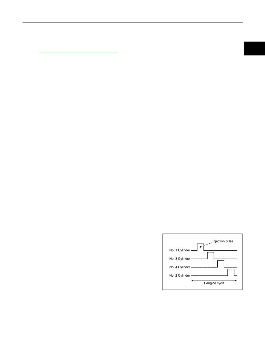
FUEL INJECTION TIMING

Fuel is injected into each cylinder during each engine cycle accord-
ing to the ignition order.

STRATIFIED-CHARGE START CONTROL

The use of the stratified-charge combustion method enables emissions-reduction when starting with the
engine cold.

FUEL SHUT-OFF

Fuel shut-off during deceleration 

Fuel to each cylinder is cut off during deceleration for restraint of HC and improvement of fuel efficiency.

JPBIA4704GB

EC-54

< SYSTEM DESCRIPTION >

[MR20DD]

SYSTEM

Engine speed at which fuel shut-off and recovery is conducted are programmed in detail according to various
factors such as idle judgment, vehicle speed, gear position, engine coolant temperature etc. for optimizing
emission and mileage performance.Also, no fuel shut-off is applied at extreme deceleration.

Fuel shut-off when the engine speed is excessively high

ECM shuts off fuel for all cylinders at the engine speed over 6,500 rpm, and recovers under 6,200 rpm.

Fuel shut-off when the engine speed is excessively high with no load

ECM shuts off fuel for all cylinders at the engine speed is high, and the vehicle speed is 0 km/h with N or P
gear position for more than certain duration.

Fuel shut-off when the engine is over heating

ECM judges as the engine is over heating and conducts fuel shut-off when the output voltage of engine cool-
ant temperature sensor exceeds the over heating judgment voltage for certain duration.
Also, malfunction indicator lamp (MIL) illuminates when the engine is judged as over heating.
And, once the engine over heating judgment is made, malfunction indicator lamp (MIL) remains ON even the
engine coolant temperature becomes low (returns to normal), then fuel will be shut off at 2,000 rpm. 
Fuel shut-off will be deactivated when the ignition key is turned OFF once, but malfunction indicator lamp
(MIL) remains ON. The deactivation of malfunction indicator lamp (MIL) can be done by clearing self diagnosis
results.

CAUTION:

Erase self diagnosis results only after the investigation of the engine over heating cause.

Fuel shut-off when N 

 D position is selected

Fuel shut-off is conducted when the engine speed is high and N 

 D position is selected.

Fuel shut-off when the engine stalls consecutively

To protect CVT, ECM conducts fuel shut-off when the engine speed is high despite the vehicle speed is exces-
sively slow for more than several minutes with gear position except N or P. This control is not conducted when
the malfunction of vehicle speed signal exists.

Fuel shut-off when malfunction indicator lamp (MIL) system is not working

ECM warns driver by conducting fuel shut-off when the request to illuminate malfunction indicator lamp (MIL)
due to some of the self diagnosis relating electric throttle system or ECM continuously exist for more than 5
trips. ECM shuts off fuel at approx. 2,500 rpm and recovers at approx. 2,000 rpm.

Fuel shut-off when the throttle stuck to closed position 

ECM conducts fuel shut-off when the electric throttle is stuck to its closed position.
But, for the sake of heating capability, ECM allows the engine start at N or P gear position with limited engine
speed.

FUEL PRESSURE CONTROL

FUEL PRESSURE CONTROL : System Description

INFOID:0000000010775038

System Diagram

JPBIA4920GB

SYSTEM

EC-55

< SYSTEM DESCRIPTION >

[MR20DD]

C

D

E

F

G

H

I

J

K

L

M

A

EC

N

P

O

SYSTEM DESCRIPTION

Low fuel pressure control

• The low fuel pressure pump is controlled by ECM and pumps fuel according to a driving condition. The

pumped fuel passes through the fuel filter and is sent to the high pressure fuel pump. 

• Low fuel pressure is adjusted by the fuel pressure regulator.

High fuel pressure control

• The high pressure fuel pump is actuated by the cam of camshaft (EXH).
• The high pressure fuel pump activates the high pressure fuel pump solenoid based on a signal received

from ECM, and adjusts the amount of discharge by changing the timing of closing the inlet checkvalve to
control fuel rail pressure.

For details about operation, refer to 

EC-34, "High Pressure Fuel Pump"

.

ELECTRIC IGNITION SYSTEM

ELECTRIC IGNITION SYSTEM : System Description

INFOID:0000000010775039

System Diagram

SYSTEM DESCRIPTION

Ignition order: 1 - 3 - 4 - 2
The ignition timing is controlled by the ECM to maintain the best air-fuel ratio for every running condition of the
engine. The ignition timing data is stored in the ECM. The ECM receives information such as the injection
pulse width and camshaft position sensor signal. Computing this information, ignition signals are transmitted
to the power transistor.

JPBIA4706GB

JPBIA4883GB

EC-56

< SYSTEM DESCRIPTION >

[MR20DD]

SYSTEM

During the following conditions, the ignition timing is revised by the ECM according to the other data stored in
the ECM.
• At starting
• During warm-up
• At idle
• At low battery voltage
• During acceleration
The basic ignition timing is programmed within the anti-knocking zone, if recommended fuel is used under dry
conditions. The knock sensor feedback control does not operate under normal driving conditions. If engine
knocking occurs, the knock sensor monitors the condition. The signal is transmitted to the ECM. The ECM
retards the ignition timing to eliminate the knocking condition.

BASIC CONTROL

• When starting, ECM controls ignition timing according to the engine speed and coolant temperature.
• After the engine is started, ECM corrects the ignition timing according to the driving conditions (engine cool-

ant temperature, accelerator pedal position, throttle position, control request from CVT etc.) based on the
engine speed and fuel injection pulse width.

• If knocking occurs, ECM retards the ignition timing within the anti-knocking control zone according to the

knocking condition.

• When the engine is idling, ECM controls the ignition timing to stabilize idling speed.
• ECM controls the duration of power transmission (power transistor ON time) to ignition coil according to the

engine speed and battery voltage.

• When the engine idle speed or the ignition timing deviates from specified value, "Idle Air Volume Learning" is

required.

CYLINDER DISTINCTION CONTROL

ECM distinguishes cylinder based on the combination of signals of crankshaft position sensor, camshaft posi-
tion sensor and the exhaust valve timing control position sensor, and if any of sensor malfunctons distin-
guishes cylinder with normal sensors.

IDLE SPEED CONTROL

IDLE SPEED CONTROL : System Description

INFOID:0000000010775040

SYSTEM DESCRIPTION

ECM conducts feedback control of the engine idle speed to the target value, by controlling intake air volume
with electric throttle, according to driving conditions such as engine warm-up condition, A/C loads, electric
loads, etc.

IDLE SPEED FEEDBACK

ECM determines control target value based on the engine coolant temperature, A/C operation status, gear
position, etc., then conducts feedback control to match the target value when idle judgment is made with
reverse/neutral position switch signal ON, or when the vehicle speed is very low.
Also, adjustment of the engine idle speed is conducted by ECM's self learning (IDLE AIR VOLUME LEARN-
ING).

CORRECTION OF BATTERY VOLTAGE

When battery voltage becomes lower than specified value, ECM corrects the target value to improve battery
charging.

OTHER CORRECTIVE CONTROLS

• When some electric load (power steering load, electric load, etc.) is turned ON, ECM controls target engine

speed for each load accordingly.

• When gear position is selected (N

D, D

N), ECM controls the engine speed by optimizing throttle opening

to minimize shift shock.

Abnormal point

Sensor to use for cylinder distinction

Crankshaft position sensor

Camshaft position sensor

Camshaft position sensor

• Crankshaft position sensor
• Exhaust valve timing control position sensor

Exhaust valve timing control position sensor

• Crankshaft position sensor
• Camshaft position sensor


содержание   ..  729  730  731  732   ..