Nissan X-Trail 32. Manual - part 732


  Главная      Nissan     Nissan X-Trail 32 - Service Manual


поиск по сайту            


содержание   ..  730  731  732  733   ..


Nissan X-Trail 32. Manual - part 732


SYSTEM

EC-57

< SYSTEM DESCRIPTION >

[MR20DD]

C

D

E

F

G

H

I

J

K

L

M

A

EC

N

P

O

• When deceleration (accelerator pedal ON

OFF), ECM controls the engine speed by optimizing throttle

opening to minimize shift shock and exhaust gas emission. 

COOLING FAN CONTROL

COOLING FAN CONTROL : System Description

INFOID:0000000010775041
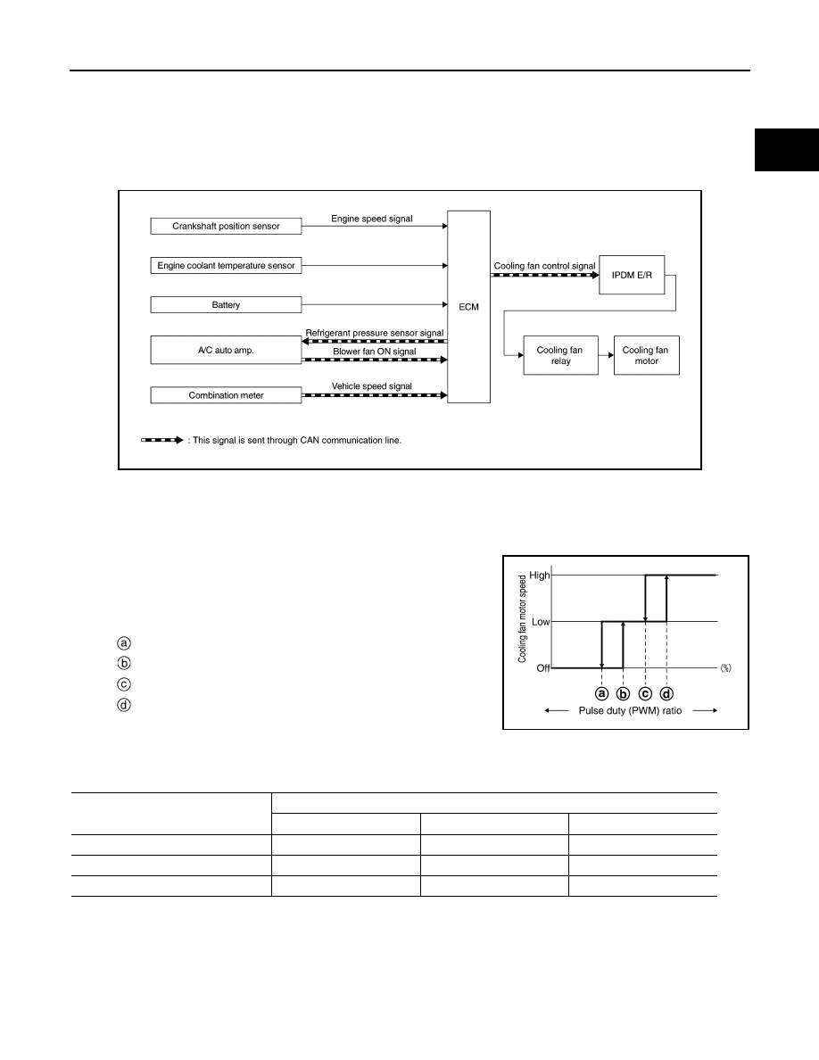
System Diagram

SYSTEM DESCRIPTION

ECM controls cooling fan speed corresponding to vehicle speed, engine coolant temperature, refrigerant pres-
sure, air conditioner ON signal. Then control system has 3-step control [ HIGH/LOW/OFF ].

Cooling Fan Operation

ECM transmits a pulse duty (PWM) signal to IPDM E/R.
IPDM E/R has threshold value to the pulse duty (PWM) signal and
operates cooling fan motor with three phases of [HI (high-speed) /
LOW (low-speed) /OFF].

Cooling Fan Relay Operation

The ECM controls cooling fan relays in IPDM E/R through CAN communication line.

INTAKE VALVE TIMING CONTROL

JSBIA5006GB

:  Less than 30% (OFF 

 low-speed)

:  More than 40% (OFF 

 low-speed)

:  Less than 50% (low-speed 

 high-speed)

:  More than 60% (low-speed 

 high-speed)

JSBIA5007GB

Cooling fan speed

Cooling fan relay

1

2

3

Stop (OFF)

OFF

OFF

OFF

Low (LOW)

OFF

ON

OFF

High (HI)

ON

OFF

ON

EC-58

< SYSTEM DESCRIPTION >

[MR20DD]

SYSTEM

INTAKE VALVE TIMING CONTROL : System Description

INFOID:0000000010775042

System Diagram

System Description

This mechanism hydraulically controls cam phases continuously with the fixed operating angle of the intake
valve.
The ECM receives signals such as crankshaft position, camshaft position, engine speed, and engine coolant
temperature. Then, the ECM sends ON/OFF pulse duty signals to the intake valve timing (IVT) control sole-
noidvalve depending on driving status. This makes it possible to control the shut/open timing of the intake
valve to increase engine torque in low/mid speed range and output in high-speed range.

Intake Valve Timing Control Solenoid Valve

Intake valve timing control solenoid valve is activated by ON/OFF pulse duty (ratio) signals from the ECM. 
Intake valve timing control solenoid valve controls the timing of intake valve opening/closing optimally by
changing duty ratio depends on the driving conditions.

JPBIA4760GB

JPBIA5034GB

SYSTEM

EC-59

< SYSTEM DESCRIPTION >

[MR20DD]

C

D

E

F

G

H

I

J

K

L

M

A

EC

N

P

O

INTAKE VALVE TIMING CONTROL FEEDBACK CONTROL

Cam Position Detection

The camshaft position sensor mounted at the rear of the cylinder head detects a cam position, by using the
groove on the plate located at the rear of the intake camshaft.

Feedback Control

The camshaft position sensor feeds back an actual cam position signal to ECM. Based on the signal, ECM
controls the intake valve timing control solenoid valve to satisfy the optimum target valve opening/closing tim-
ing according to a driving condition.

EXHAUST VALVE TIMING CONTROL

EXHAUST VALVE TIMING CONTROL : System Description

INFOID:0000000010775043

System Diagram

SYSTEM DESCRIPTION

With the exhaust valve timing controller which controls the phase of exhaust camshaft to optional position con-
tinuously, ECM improves both low-middle speed torque and high speed performance, emission and fuel effi-
ciency by optimizing the exhaust valve open/close timing according to driving conditions.
The exhaust valve timing controller is hydraulically controlled by the exhaust valve timing control solenoid
valve.

Status of intake valve timing so-

lenoid valve

Intake valve timing controller activation

Engine OFF

When starting the engine, the controller vane and sprocket are fixed in full retard position by the 
reaction force of return spring, improving the starting performance of the engine.

Active (Advanced angle)

When the energization rate to the control solenoid valve is increased, the oil pressure from the oil 
pump is conveyed to the advance angle chamber of the controller. And retard angle chamber oil is 
drained. 
Accordingly, the controller vane rotates rightward and the phase of camshaft becomes advance an-
gle.
This condition brings about the greater overlap with the exhaust valve, enabling the exhaust gas 
cleaning by the internal EGR effect and the fuel consumption improvement by the reduction in 
pumping loss.

Neutral (Maintained)

When it is the target valve timing, the energization rate to the control solenoid valve is adjusted to 
the intermediate state. The solenoid valve is positioned at the neutral position and the oil path is 
interrupted to maintain the cam shaft phase.

Return (Retard angle)

When the energization rate to the control solenoid valve is decreased, the oil pressure from the oil 
pump is conveyed to the retard chamber of the controller. And advanced angle chamger oil is 
drained.
Accordingly, the controller vane rotates leftward and the phase of camshaft becomes retard angle.

JSBIA5015GB

EC-60

< SYSTEM DESCRIPTION >

[MR20DD]

SYSTEM

This mechanism hydraulically controls cam phases continuously with the fixed operating angle of the exhaust
valve.
The ECM receives signals such as crankshaft position, camshaft position, engine speed, and engine oil tem-
perature. Then, the ECM sends ON/OFF pulse duty signals to the exhaust valve timing control solenoid valve
depending on driving status. This makes it possible to control the shut/open timing of the exhaust valve to
increase engine torque and output in a range of high engine speed.

EXHAUST VALVE TIMING CONTROL SOLENOID VALVE CONTROL

The exhaust valve timing control solenoid valve is driven ON-OFF (duty control) by ECM output signal, and
controls the open/close timing of the exhaust valve to the optimum by changing its duty ratio according to the
vehicle's driving condition.

EXHAUST VALVE TIMING CONTROL FEEDBACK CONTROL

JPBIA5035GB

Exhaust valve timing control so-

lenoid valve condition

Exhaust valve timing controller operation

Engine OFF

When starting the engine, the controller vane and sprocket are fixed in full advanced position by the 
reaction force of return spring, improving the starting performance of the engine.

Active (Retard angle)

When the energization rate to the control solenoid valve is increased, the oil pressure from the oil 
pump is conveyed to the retard angle chamber of the controller. And advanced angle chamber oil 
is drained. Accordingly, the controller vane rotates leftward and the phase of camshaft becomes re-
tard angle.This condition brings about the greater overlap with the intake valve, enabling the ex-
haust gas cleaning by the internal EGR effect and the fuel consumption improvement by the 
reduction in pumping loss.

Neutral (Maintained)

When it is the target valve timing, the energization rate to the control solenoid valve is adjusted to 
the intermediate state. The solenoid valve is positioned at the neutral position and the oil path is 
interrupted to maintain the cam shaft phase.

Return (Advanced angle)

When the energization rate to the control solenoid valve is decreased, the oil pressure from the oil 
pump is conveyed to the advanced chamber of the controller. And retard angle chamber oil is 
drained.Accordingly, the controller vane rotates rightward and the phase of camshaft becomes ad-
vanced angle.


содержание   ..  730  731  732  733   ..