Nissan X-Trail 32. Manual - part 734


  Главная      Nissan     Nissan X-Trail 32 - Service Manual


поиск по сайту            


содержание   ..  732  733  734  735   ..


Nissan X-Trail 32. Manual - part 734


SYSTEM

EC-65

< SYSTEM DESCRIPTION >

[MR20DD]

C

D

E

F

G

H

I

J

K

L

M

A

EC

N

P

O

ECO MODE SYSTEM : System Description

INFOID:0000000010775048
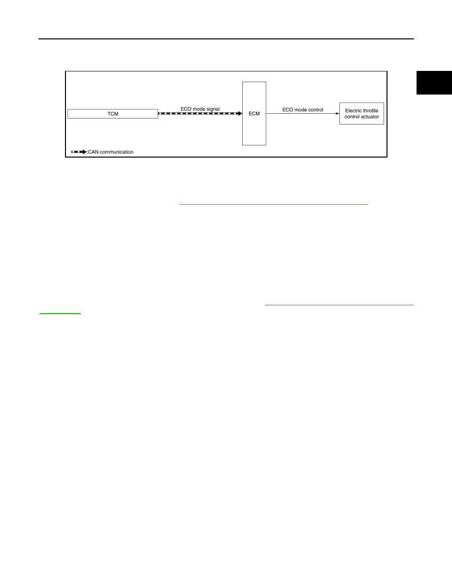
System Diagram

CONTROL

ECM receives an ECO mode signal from TCM via CAN communication and improves the fuel economy by
controlling the throttle movement to less than usual.
NOTE:
For the details of the ECO mode, refer to

DMS-7, "ECO MODE CONTROL : System Description"

.

SYSTEM DISPLAY FUNCTION

ECO Mode Indicator Lamp

When the ECM receives ECO mode signal from TCM, ECM transmits an ECO mode indicator lamp signal to
the combination meter via CAN communication, and the combination meter illuminates ECO mode indicator
located in itself.

ECO DRIVE NAVIGATOR

ECM transmits an ECO drive navigator signal calculated from the accelerator pedal position and the vehicle
speed to the combination meter via CAN communication.
When the acceleration guide is selected in ECO meter display switching function, the suitable accelerator
position for fuel economy will be displayed. For display, refer to .

DMS-7, "ECO MODE CONTROL : System

Description"

.

INTEGRATED CONTROL OF ENGINE, CVT, AND ABS

INTEGRATED CONTROL OF ENGINE, CVT, AND ABS : System Description

INFOID:0000000010775049

Real time communications (signal exchange) among control units (e.g. ECM, CVT, ABS, and combination
meter) via CAN communication optimizes engine torque and lock-up during gear shift and prevents engine
speed from decreasing during deceleration.

EVAPORATIVE EMISSION SYSTEM

JSBIA5010GB

EC-66

< SYSTEM DESCRIPTION >

[MR20DD]

SYSTEM

EVAPORATIVE EMISSION SYSTEM : System Description

INFOID:0000000010775050

System Diagram

System Description

The evaporative emission system is used to reduce hydrocarbons emitted into the atmosphere from the fuel-
system.
The evaporative emission system is used to reduce hydrocarbons emitted into the atmosphere from the fuel
system. This reduction of hydrocarbons is accomplished by activated charcoals in the EVAP canister.
The fuel vapor in the sealed fuel tank is led into the EVAP canister which contains activated carbon and the
vapor is stored there when the engine is not operating or when refueling to the fuel tank. 
The vapor in the EVAP canister is purged by the air through the purge line to the intake manifold when the
engine is operating. EVAP canister purge volume control solenoid valve is controlled by ECM. When the
engine operates, the flow rate of vapor controlled by EVAP canister purge volume control solenoid valve is
proportionally regulated as the air flow increases. EVAP canister purge volume control solenoid valve also
shuts off the vapor purge line during decelerating and idling.

POWER GENERATION VOLTAGE VARIABLE CONTROL SYSTEM

POWER GENERATION VOLTAGE VARIABLE CONTROL SYSTEM : System De-
scription

INFOID:0000000010775051

DESCRIPTION

ECM transmits a target power generation voltage signal received from IPDM E/R to the generator via LIN
communication.

JSBIA0322GB

PBIB3039E

SYSTEM

EC-67

< SYSTEM DESCRIPTION >

[MR20DD]

C

D

E

F

G

H

I

J

K

L

M

A

EC

N

P

O

The generator includes a self-diagnosis function and transmits a diagnosis signal to ECM via LIN communica-
tion when detecting a malfunction. When ECM receives a diagnosis signal, ECM detects DTC and transmits a
charge warning lamp request signal to the combination meter to turn ON the charge warning lamp.

INFORMATION DISPLAY (COMBINATION METER)

INFORMATION DISPLAY (COMBINATION METER) : Indicator/Information

INFOID:0000000010775052

INFORMATION DISPLAY (COMBINATION METER) : Engine Oil Pressure Warining

INFOID:0000000010775053

DESIGN/PURPOSE

When engine oil pressure is low, the engine oil pressure warning lamp informs the driver of low oil pressure to
prevent damage to the engine.

BULB CHECK

The bulb turns ON after turning ON the ignition switch (engine stop) and turns OFF after restarting the engine.

OPERATION AT COMBINATION METER CAN COMMUNICATION CUT-OFF OR UNUSUAL SIG-
NAL

For the operation for CAN communications blackout or abnormal signal reception, refer to 

EC-103, "Fail-safe"

.

Item

Symbol

Function

ASCD indicator

For detail of ASCD function, refer to 

EC-64, "AUTO-

MATIC SPEED CONTROL DEVICE (ASCD) : Sys-
tem Description"

.

Massage: - - Km/h / - - MPH

JSCIA0831ZZ

Symbol

Message

Low Oil Pressure
Stop Vehicle

JPNIA1881ZZ

EC-68

< SYSTEM DESCRIPTION >

[MR20DD]

SYSTEM

SYSTEM DIAGRAM

SIGNAL PATH

• ECM reads the resistance value of an engine oil pressure sensor and transmits the engine oil pressure

warning signal to combination meter via CAN communication.

• The information display (on combination meter) is SHOWN/HIDDEN the engine oil pressure warning,

according to the engine oil pressure sensor signal received from ECM.

LIGHTING CONDITION

When all of the following conditions are satisfied:

• Ignition switch: ON
• Engine running
• Engine oil pressure is less than the specified value.

SHUTOFF CONDITION

• Ignition switch: OFF
• Engine stop
• Engine oil pressure is the specified value or more.

TIMING CHART

WARNING/INDICATOR/CHIME LIST

WARNING/INDICATOR/CHIME LIST : Warning lamps/Indicator lamps

INFOID:0000000010775054

NOTE:
Regarding the arrangement. Refer to 

MWI-10, "METER SYSTEM : Design"

.

JSBIA3494GB

JSBIA3700GB

t

: 100 ms

Item

Design

Reference

Malfunction indicator lamp (MIL)

Regarding the function. Refer to 

MWI-50, "WARNING LAMPS/INDICATOR 

LAMPS : Malfunction Indicator Lamp (MIL)"

.


содержание   ..  732  733  734  735   ..