содержание .. 319 320 321 322 ..
Nissan X-Trail 32. Manual - part 321
DAS
SYSTEM
DAS-25
< SYSTEM DESCRIPTION >
[DRIVER ASSISTANCE SYSTEM]
C
D
E
F
G
H
I
J
K
L
M
B
N
P
A
Operation Condition
• DAA: ON
• Vehicle speed approximately 60 km/h or more
NOTE:
• DAA system ON/OFF can be set on the combination meter.
• When the engine is stopped, the system is reset.
• The DAA system may not function properly, depending on the situation. Refer to
.
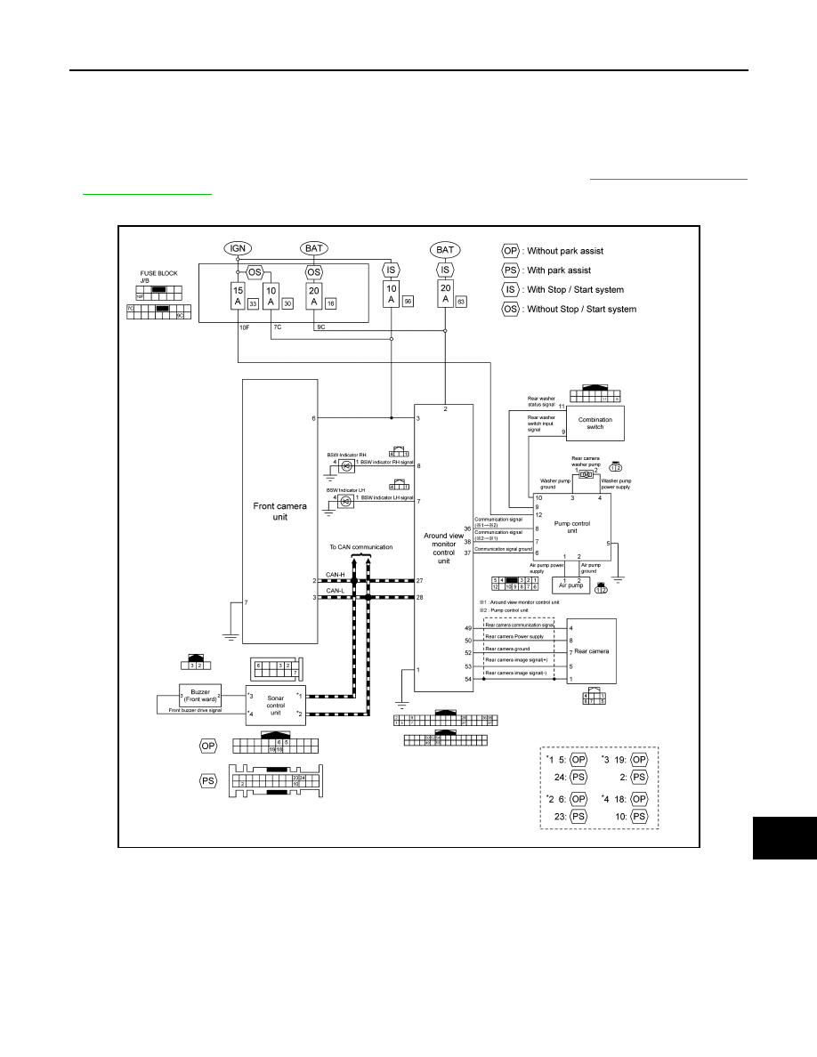
Circuit Diagram
INFOID:0000000010727890
Fail-safe (Front Camera Unit)
INFOID:0000000010924936
FAIL-SAFE CONTROL BY DTC
LDW (Lane Departure Warning)
If a malfunction occurs in front camera unit, front camera unit cancels control, and turns ON the LDW malfunc-
tion in information display.
TSR (Traffic Sign Recognition)
JSOIA1660GB