Nissan X-Trail 32. Manual - part 320


  Главная      Nissan     Nissan X-Trail 32 - Service Manual


поиск по сайту            


содержание   ..  318  319  320  321   ..


Nissan X-Trail 32. Manual - part 320


DAS

SYSTEM

DAS-21

< SYSTEM DESCRIPTION >

[DRIVER ASSISTANCE SYSTEM]

C

D

E

F

G

H

I

J

K

L

M

B

N

P

A

TSR : System Description

INFOID:0000000010795655
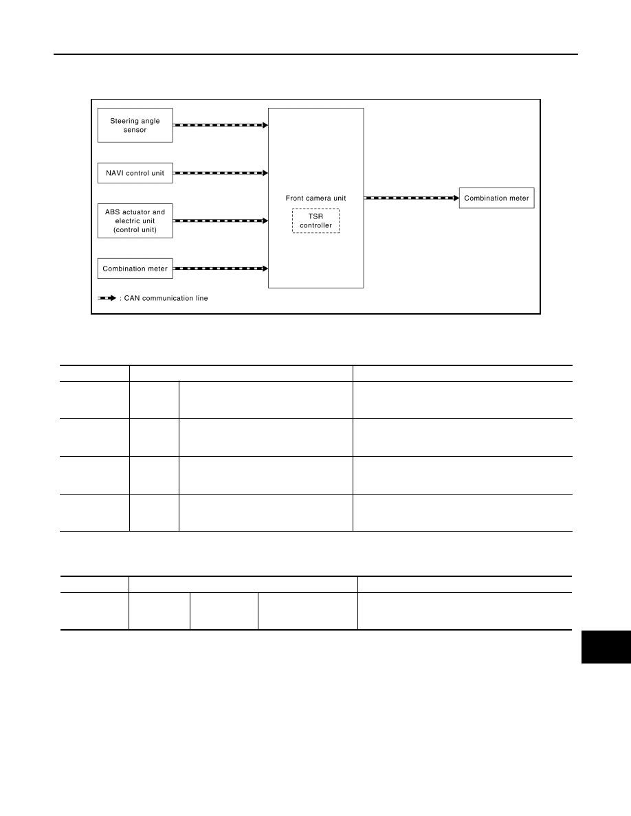
SYSTEM DIAGRAM

FRONT CAMERA UNIT INPUT/OUTPUT SIGNAL ITEM

Input Signal Item

*: With navigation system

Output Signal Item

FUNCTION DESCRIPTION

Displays the road conditions as identified by the front camera unit on the information display, and alerts the
driver. Identifies the road sign information.
The front camera unit detects road signs as described below and displays them on the information display.

JSOIA1658GB

Transmit unit

Signal name

Description

ABS actuator 
and electric unit 
(control unit)

CAN com-
munica-
tion

Vehicle speed signal (ABS)

Receives the wheel speed of the four wheels

Combination 
meter

CAN com-
munica-
tion

System selection signal

Receives a selection state of each item in “Driver Aids” 
selected with the combination meter

NAVI control 

unit

*

CAN com-
munica-
tion

Speed limit information signal

Receives the speed limit information data in the NAVI 
control unit

Steering angle 
sensor

CAN com-
munica-
tion

Steering angle sensor signal

Receives the number of revolutions, turning direction of 
the steering wheel

Reception unit

Signal name

Description

Combination 
meter

CAN commu-
nication

Meter display 
signal

• Speed limit sign sig-

nal

• Do not pass sign

Transmits a signal and displays the status on the ve-
hicle information display

DAS-22

< SYSTEM DESCRIPTION >

[DRIVER ASSISTANCE SYSTEM]

SYSTEM

*1: Displayed when TSR is ON and road signs are not recognized. 
*2: Displayed when a supplemental sign other than those from 

 to 

 is detected.

Latest detected speed limit

National speed limit

No-overtaking zone

End of no-overtaking zone

Conditional speed limit

No road sign information

*1

Snow

Slip (rain 1)

Rain (rain 2)

Towing

Generic

*2

JSOIA1626ZZ

DAS

SYSTEM

DAS-23

< SYSTEM DESCRIPTION >

[DRIVER ASSISTANCE SYSTEM]

C

D

E

F

G

H

I

J

K

L

M

B

N

P

A

EXAMPLE

OPERATION DESCRIPTION

• The TSR system is controlled by the front camera unit.
• The front camera unit turns on the TSR system when the turned ON by combination meter.
• The front camera unit detects the road sign.
• The front camera unit transmits the meter display signal to the combination meter, when detecting the road

sign.

• The front camera unit receives the speed limit information data from the NAVI control unit. (With navigation

system)

• The front camera unit detects speed limit signs, recognizes speed limit signs by combining the detected

speed limit signs with speed limit information data received from the NAVI control unit, and transmits a meter
display signal to the combination meter. (With navigation system)

• The front camera unit adjusts the detection range of road signs according to a steering angle sensor signal

received from the steering angle sensor.

Operation Condition

• TSR: ON
NOTE:
• TSR system ON/OFF can be set on the combination meter
• The TSR system may not function properly, depending on the situation. Refer to 

DAS-41, "Precautions for

Traffic Sign Recognition"

.

DAA

JSOIA1617ZZ

DAS-24

< SYSTEM DESCRIPTION >

[DRIVER ASSISTANCE SYSTEM]

SYSTEM

DAA : System Description

INFOID:0000000010795656

SYSTEM DIAGRAM

AROUND VIEW MONITOR CONTROL UNIT INPUT/OUTPUT SIGNAL ITEM

Input Signal Item

Output Signal Item

FUNCTION DESCRIPTION

• Operates when the vehicle speed is 60 km/h or higher.
• Detects the steering status and judges the attentiveness of the driver. The driver's attentiveness is shown on

the vehicle information display in eight stages (level indicator).

• When it is judged from the degree of minor swerving in the steering operation that the vehicle is drifting, the

driver is prompted to exert caution by the drift warning, which displays on the combination meter, and by a
buzzer sound.

• When the engine is stopped, the system is reset.
• When the level indicator on the drift warning display becomes 1, the system warns the driver with a buzzer

sound.

OPERATION DESCRIPTION

• The DAA (Driver Attention Alert) is controlled by the around view monitor control unit.
• ON/OFF of the DAA is performed by using the combination meter.
• The steering angle sensor detects the degree of swerving in the steering operation.
• When the around view monitor control unit judges that the steering operation is drifting (when the level indi-

cator in the drift warning display becomes 1), the following control is performed and the driver is warned.

- Transmits the buzzer output signal to the combination meter and sounds the buzzer.

JSOIA1659GB

Transmit unit

Signal name

Description

ABS actuator 
and electric unit 
(control unit)

CAN com-
munica-
tion

Vehicle speed signal (ABS)

Receives the wheel speed of the four wheels

Combination 
meter

CAN com-
munica-
tion

System selection signal

Receives a selection state of each item in “Driver Assis-
tance” selected with the combination meter

Steering angle 
sensor

CAN com-
munica-
tion

Steering angle sensor signal

Receives the amount of rotation, rotational angle, and 
rotational direction of the steering wheel

Reception unit

Signal name

Description

Combination 
meter

CAN commu-
nication

Meter display 
signal

• Speed limit sign sig-

nal

• Do not pass sign

Transmits a signal and displays the status on the ve-
hicle information display

Buzzer output signal

Operates the buzzer


содержание   ..  318  319  320  321   ..