содержание .. 316 317 318 319 ..
Nissan X-Trail 32. Manual - part 318
DAS
COMPONENT PARTS
DAS-13
< SYSTEM DESCRIPTION >
[DRIVER ASSISTANCE SYSTEM]
C
D
E
F
G
H
I
J
K
L
M
B
N
P
A
*: For vehicles without sonar system, meter buzzer is used.
Combination Meter
INFOID:0000000010727881
• Receives meter display signal and buzzer output signal
*
from around view monitor control unit via CAN com-
munication.
• Displays the each system operation status according to meter display signal received form the around view
monitor control unit.
• Operates the buzzer according to the signal from the around view monitor control unit.
*
• Transmits the ambient temperature signal to around view monitor via CAN communication.
*: For vehicles with sonar system, sonar buzzer is used.
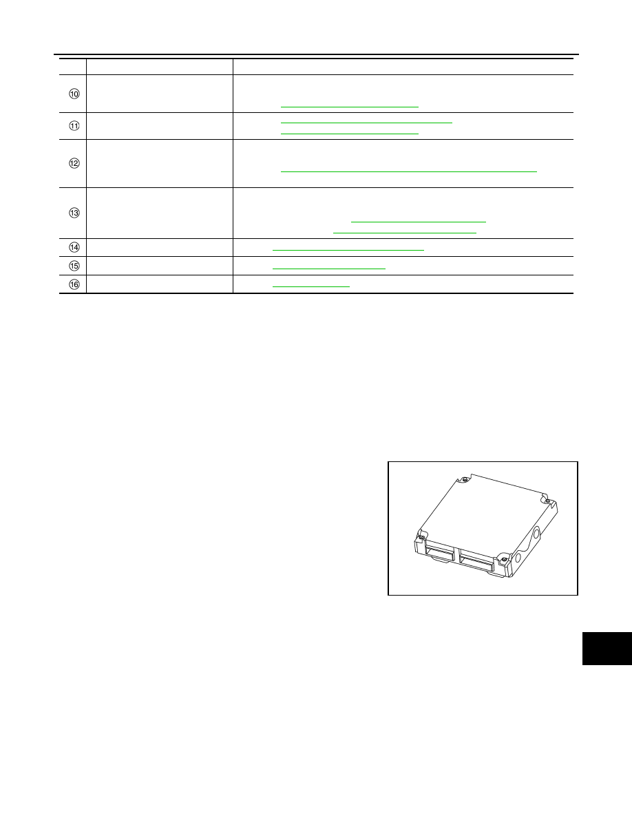
Around View Monitor Control Unit
INFOID:0000000010727882
• The around view monitor control unit is installed behind the glove
box.
• The around view monitor control unit controls following systems
according to the signals via CAN communication from each control
unit.
- BSW
- DAA
BSW Indicator LH/RH
INFOID:0000000010727883
• BSW indicator is installed in the door mirror corner cover.
• Receives a BSW indicator operation signal from the around view monitor control unit and blinks or turns ON/
OFF the BSW indicator.
Rear Camera
INFOID:0000000010727884
• The rear view camera is installed to the back door finisher.
• With the mirror processing function, a mirror image is sent as if it is viewed by a rear view mirror.
• Power for the camera is supplied from the around view monitor control unit, and the image at the rear of the
vehicle is sent to the around view monitor control unit.
• The rear camera is equipped with a washer nozzle and air nozzle for cleaning camera. A check valve is
installed to the tube connected to the washer nozzle.
NAVI control unit
• Transmits the speed limit information signal to the front camera unit via CAN commu-
nication
AV-64, "Component Parts Location"
for detailed installation location
Around view monitor control unit
DAS-13, "Around View Monitor Control Unit"
AV-64, "Component Parts Location"
for detailed installation location
BCM
• Transmits the turn indicator signal and position light request signal to around view
monitor via CAN communication
BCS-6, "BODY CONTROL SYSTEM : Component Parts Location"
for de-
tailed installation location
Buzzer
• The warning buzzer sounds with the signal from the sonar control unit
*
• Refer to following for detailed installation location
- WITHOUT PARK ASSIST:
SN-8, "Component Parts Location"
- WITH PARK ASSIST:
SN-119, "Component Parts Location"
Rear camera washer pump
Refer to
DAS-15, "Rear Camera Washer Pump"
Pump control unit
Refer to
Air pump
Refer to
No.
Component
Function
JSOIA0646ZZ