Nissan X-Trail 32. Manual - part 319


  Главная      Nissan     Nissan X-Trail 32 - Service Manual


поиск по сайту            


содержание   ..  317  318  319  320   ..


Nissan X-Trail 32. Manual - part 319


DAS

SYSTEM

DAS-17

< SYSTEM DESCRIPTION >

[DRIVER ASSISTANCE SYSTEM]

C

D

E

F

G

H

I

J

K

L

M

B

N

P

A

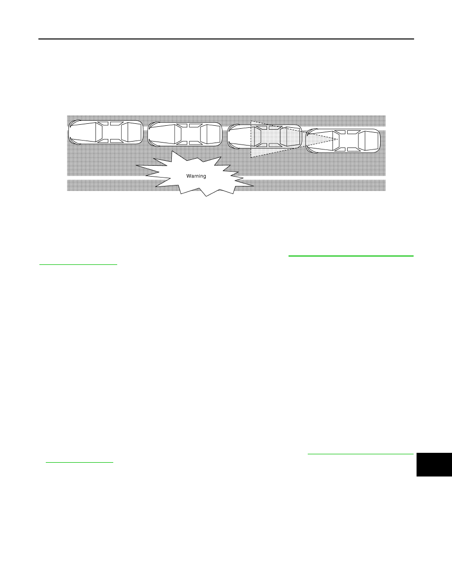
• When the vehicle approaches either the left or the right side of the traveling lane, a warning will alert the

driver (the buzzer and the display on the combination meter).

• The warning does not occur during turn signal operation (Lane change side).
• The warning function will stop when the vehicle returns inside of the lane markers.

EXAMPLE

When the vehicle approaches the right lane marker, the driver is alerted by the buzzer and the display on the
combination meter.
NOTE:
For details of LDW system indication on the combination meter, refer to 

DAS-30, "LDW : Menu Displayed by

Pressing Each Switch"

.

OPERATION DESCRIPTION

• LDW system is controlled by the front camera unit.
• When the system is turned ON, the front camera unit transmits LDW system display signal to combination

meter via CAN communication.

• The front camera unit monitors lane markers of the traveling lane.
• When judging from a lane marker detection signal that the vehicle is approaching the lane marker, the front

camera unit controls the following item to alert the driver.

- Activates warning buzzer in the sonar control unit (With sonar system) or combination meter (Without sonar

system).

- The front camera unit transmits a LDW system display signal to combination meter via CAN communication

and blinks the LDW system indicator (“icon”).

Operating Condition

• LDW system indicator (white): ON (“lane”)

When the LDW system setting on the combination meter is ON

• Vehicle speed: approximately 60 km/h (37 MPH) or more
• Turn indicator signal: After 2 seconds or more from turned OFF
NOTE:
• LDW system ON/OFF can be set on the combination meter
• After the operating conditions of warning are satisfied, the warning continues until the vehicle speed reaches

approximately 55 km/h (34 MPH)

• LDW system may not function properly, depending on the situation. Refer to 

DAS-40, "Precautions for Lane

Departure Warning"

.

BSW

JPOIA0014GB

DAS-18

< SYSTEM DESCRIPTION >

[DRIVER ASSISTANCE SYSTEM]

SYSTEM

BSW : System Description

INFOID:0000000010727889

SYSTEM DIAGRAM

AROUND VIEW MONITOR CONTROL UNIT INPUT/OUTPUT SIGNAL ITEM

Around view monitor control unit receives signals via CAN communication. It also detects vehicle conditions
that are necessary for BSW control.

Input Signal Item

JSOIA1657GB

DAS

SYSTEM

DAS-19

< SYSTEM DESCRIPTION >

[DRIVER ASSISTANCE SYSTEM]

C

D

E

F

G

H

I

J

K

L

M

B

N

P

A

Output Signal Item

*1: Without sonar system
*2: With sonar system

FUNCTION DESCRIPTION

• The BSW system can help alert the driver of other vehicles in adjacent lanes when changing lanes.
• The BSW system uses rear camera installed the back door finisher to detect vehicles in an adjacent lane.
• The rear camera can detect vehicles on either side of vehicle within the detection zone shown as illustrated.
• This detection zone starts from the outside mirror of vehicle and extends approximately 10 ft (3.0 m) behind

the rear bumper, and approximately 10 ft (3.0 m) sideways.

• The BSW system operates above approximately 32 km/h (20 MPH).
• If the rear camera detects vehicles in the detection zone, the BSW indicator illuminates.

Transmit unit

Signal name

Description

ABS actuator 
and electric unit 
(control unit)

CAN com-
munica-
tion

Vehicle speed signal (ABS)

Receives wheel speeds of four wheels

BCM

CAN com-
munica-
tion

Turn indicator signal

Receives an operational state of the turn signal lamp 
and the hazard lamp

Position light request signal

Receives an operational state of tail lamp

Combination 
meter

CAN com-
munica-
tion

System selection signal

Receives a selection state of each item in “Driver Aids” 
selected with the combination meter

Ambient sensor signal

Receives the ambient temperature

Steering angle 
sensor

CAN com-
munica-
tion

Steering angle sensor signal

Receives the number of revolutions, turning direction of 
the steering wheel

ECM

CAN com-
munica-
tion

Engine status signal

Receives the engine status

Engine coolant temperature signal

Receives the engine coolant temperature

Reception unit

Signal name

Description

Combination 
meter

CAN communication

Meter dis-
play signal

BSW system dis-
play signal

Transmits a meter display signal to turn ON the Blind 
Spot Warning system display

Buzzer output signal

*1

Transmits a buzzer output signal to activates the 
warning buzzer

Pump control 
unit

Communication line

Rear camera washer signal

Transmits a rear camera washer signal to activates 
the washer pump

Rear camera air blow signal

Transmits a rear camera air blow signal to activates 
the air pump

Sonar control 

unit

*2

CAN communication

Buzzer drive signal

Transmits a buzzer drive signal to activate buzzer

JSOIA0642ZZ

DAS-20

< SYSTEM DESCRIPTION >

[DRIVER ASSISTANCE SYSTEM]

SYSTEM

• If the driver then activates the turn signal, a buzzer will sound twice and the BSW indicator will blink.

NOTE:
A buzzer sounds if the rear camera have already detected vehicles when the driver activates the turn signal.
If a vehicle comes into the detection zone after the driver activates the turn signal, then only the BSW indica-
tor blinks and no buzzer sounds.

OPERATION DESCRIPTION

• Around view monitor control unit enables BSW system.
• The around view monitor control unit turns on the BSW system when the turned ON by combination meter.
• Rear camera transmits the camera image signal to around view monitor control unit.
• Around view monitor control unit starts the control as follows, based on a camera image signal, turn indicator

signal and position light request signal transmitted from BCM via CAN communication:

- Buzzer drive signal transmission to sonar control unit via CAN communication. (With sonar system)
- Buzzer output signal transmission to combination meter via CAN communication. (Without sonar system)
• Around view monitor control unit transmits an indicator operation signal to the BSW indicator.

Operation Condition

• BSW system indicator (white): ON (Speaker icon ON in “Blind spot” position) 
• When the vehicle drives at 32 km/h (20 MPH) or more to the forward direction.
NOTE:
BSW system ON/OFF can be set on the combination meter 
• After the operating conditions of warning are satisfied, the warning continues until the vehicle speed reaches

approximately 29 km/h (18 MPH)

• The BSW system may not function properly, depending on the situation. Refer to 

DAS-40, "Precautions for

Blind Spot Warning"

.

TSR

JSOIA0643ZZ


содержание   ..  317  318  319  320   ..