Nissan X-Trail 32. Manual - part 2188


  Главная      Nissan     Nissan X-Trail 32 - Service Manual


поиск по сайту            


содержание   ..  2186  2187  2188  2189   ..


Nissan X-Trail 32. Manual - part 2188


TM-710

< SERVICE DATA AND SPECIFICATIONS (SDS) 

[CVT: RE0F10G]

SERVICE DATA AND SPECIFICATIONS (SDS)

SERVICE DATA AND SPECIFICATIONS (SDS)

SERVICE DATA AND SPECIFICATIONS (SDS)

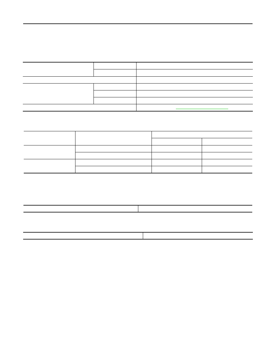
General Specification

INFOID:0000000010622936

Shift Characteristics

INFOID:0000000010622937

Unit: rpm

NOTE:
Lock-up is engaged at the vehicle speed of approximately 14 km/h (9 MPH) to 40 km/h (24 MPH). 

Stall Speed

INFOID:0000000010622938

Unit: rpm

Torque Converter

INFOID:0000000010622939

Unit: mm (in)

Applied model

Engine

R9M

Axle

2WD

Transaxle model

RE0F10G

Transaxle gear ratio

D position

2.413 – 0.383

R position

1.798

Final drive

5.577

Recommended fluid and fluid capacity

Refer to 

MA-23, "Fluids and Lubricants"

.

 Throttle position

Shift pattern

CVT input speed

At 40 km/h (25 MPH)

At 60 km/h (37 MPH)

2/8

“D” position (Normal)

1,470 – 2,510

1,570 – 3,200

“D” position (ECO)

1,470 – 2,510

1,570 – 3,200

8/8

“D” position (Normal)

3,430 – 4,030

4,100 – 4,700

“D” position (ECO)

3,430 – 4,030

4,100 – 4,700

Stall speed

2,670 – 3,010

Dimension “A” between the converter housing and torque converter

18.1 (0.713)

VTL-1

VENTILATION, HEATER & AIR CONDITIONER

C

D

E

F

G

H

J

K

L

M

SECTION 

VTL

A

B

VTL

N

O

P

CONTENTS

VENTILATION SYSTEM

PRECAUTION ...............................................

2

PRECAUTIONS ...................................................

2

Precaution for Supplemental Restraint System 
(SRS) "AIR BAG" and "SEAT BELT PRE-TEN-
SIONER" .................................................................
..

2

Precaution Necessary for Steering Wheel Rota-
tion After Battery Disconnect ...................................
..

2

Precautions for Removing Battery Terminal  .............

3

SYSTEM DESCRIPTION  ..............................

5

VENTILATION SYSTEM  .....................................

5

System Description  ...................................................

5

REMOVAL AND INSTALLATION ................

7

DUCT AND GRILLE ............................................

7

Exploded View  ..........................................................

7

CENTER VENTILATOR GRILLE  ................................

8

CENTER VENTILATOR GRILLE : Removal and 
Installation ...............................................................
..

8

SIDE VENTILATOR GRILLE .......................................

9

SIDE VENTILATOR GRILLE : Removal and In-
stallation ..................................................................
..

9

CENTER VENTILATOR DUCT ..................................

10

CENTER VENTILATOR DUCT : Removal and In-
stallation ..................................................................

10

FRONT DEFROSTER NOZZLE  ................................

11

FRONT DEFROSTER NOZZLE : Removal and In-
stallation ..................................................................

11

SIDE DEFROSTER NOZZLE  ....................................

11

SIDE DEFROSTER NOZZLE : Removal and In-
stallation ..................................................................

11

SIDE DEFROSTER GRILLE  .....................................

12

SIDE DEFROSTER GRILLE : Removal and In-
stallation ..................................................................

12

FOOT DUCT ...............................................................

12

FOOT DUCT : Removal and Installation  .................

12

REAR FLOOR DUCT 1 ..............................................

13

REAR FLOOR DUCT 1 : Removal and Installation 

....

13

REAR FLOOR DUCT 2 ..............................................

13

REAR FLOOR DUCT 2 : Removal and Installation 

....

13

REAR VENTILATOR DUCT 1  ...................................

13

REAR VENTILATOR DUCT 1 : Removal and In-
stallation ..................................................................

13

REAR VENTILATOR DUCT 2  ...................................

14

REAR VENTILATOR DUCT 2 : Removal and In-
stallation ..................................................................

14

REAR VENTILATOR GRILLE  ...................................

14

REAR VENTILATOR GRILLE : Removal and In-
stallation ..................................................................

14

BLOWER MOTOR  ............................................

15

Exploded View .........................................................

15

Removal and Installation  .........................................

15

AIR CONDITIONER FILTER .............................

16

Exploded View .........................................................

16

Removal and Installation  .........................................

16

Replacement ...........................................................

16

SERVICE DATA AND SPECIFICATIONS 
(SDS) ............................................................

17

SERVICE DATA AND SPECIFICATIONS 
(SDS) .................................................................

17

Air Conditioner Filter ................................................

17

VTL-2

< PRECAUTION >

PRECAUTIONS

PRECAUTION

PRECAUTIONS

Precaution for Supplemental Restraint System (SRS) "AIR BAG" and "SEAT BELT 
PRE-TENSIONER"

INFOID:0000000010981797

The Supplemental Restraint System such as “AIR BAG” and “SEAT BELT PRE-TENSIONER”, used along
with a front seat belt, helps to reduce the risk or severity of injury to the driver and front passenger for certain
types of collision. Information necessary to service the system safely is included in the “SRS AIR BAG” and
“SEAT BELT” of this Service Manual.

WARNING:

Always observe the following items for preventing accidental activation.
• To avoid rendering the SRS inoperative, which could increase the risk of personal injury or death in

the event of a collision that would result in air bag inflation, all maintenance must be performed by
an authorized NISSAN/INFINITI dealer.

• Improper maintenance, including incorrect removal and installation of the SRS, can lead to personal

injury caused by unintentional activation of the system. For removal of Spiral Cable and Air Bag
Module, see “SRS AIR BAG”.

• Never use electrical test equipment on any circuit related to the SRS unless instructed to in this Ser-

vice Manual. SRS wiring harnesses can be identified by yellow and/or orange harnesses or harness
connectors.

PRECAUTIONS WHEN USING POWER TOOLS (AIR OR ELECTRIC) AND HAMMERS

WARNING:

Always observe the following items for preventing accidental activation.
• When working near the Air Bag Diagnosis Sensor Unit or other Air Bag System sensors with the

ignition ON or engine running, never use air or electric power tools or strike near the sensor(s) with
a hammer. Heavy vibration could activate the sensor(s) and deploy the air bag(s), possibly causing
serious injury.

• When using air or electric power tools or hammers, always switch the ignition OFF, disconnect the

battery, and wait at least 3 minutes before performing any service.

Precaution Necessary for Steering Wheel Rotation After Battery Disconnect

INFOID:0000000011014464

CAUTION:

Comply with the following cautions to prevent any error and malfunction.
• Before removing and installing any control units, first turn the ignition power source and accessory

power source to the OFF, then disconnect both battery cables.

• After finishing work, confirm that all control unit connectors are connected properly, then re-connect

both battery cables.

• Always use CONSULT to perform self-diagnosis as a part of each function inspection after finishing

work. If a DTC is detected, perform trouble diagnosis according to self-diagnosis results.

For vehicle with steering lock unit, if the battery is disconnected or discharged, the steering wheel will lock and
cannot be turned.
If turning the steering wheel is required with the battery disconnected or discharged, follow the operation pro-
cedure below before starting the repair operation.

OPERATION PROCEDURE

1.

Connect both battery cables.
NOTE:
Supply power using jumper cables if battery is discharged.

2.

Open driver door.

3.

Turn the ignition switch to the ON position.
(At this time, the steering lock will be released.)

4.

Turn the ignition switch to OFF position with driver door open.

5.

Wait for 3 minutes or longer with driver door open.
NOTE:
• Do not close driver door because the steering wheel locks when driver door is closed.

PRECAUTIONS

VTL-3

< PRECAUTION >

C

D

E

F

G

H

J

K

L

M

A

B

VTL

N

O

P

• The auto acc function is adapted to this vehicle. For this reason, even when the ignition switch is turned

to OFF position, the accessory power source does not turned OFF and continues to be supplied for a
certain amount of time.

6.

Disconnect both battery cables. The steering lock will remain released with both battery cables discon-
nected and the steering wheel can be turned.

7.

Perform the necessary repair operation.

8.

When the repair work is completed, re-connect both battery cables. With the brake pedal released, turn
the ignition switch from OFF position to ON position, then to LOCK position. (The steering wheel will lock
when the ignition switch is turned to LOCK position.)

9.

Perform self-diagnosis check of all control units using CONSULT.

Precautions for Removing Battery Terminal

INFOID:0000000011014465

• With the adoption of Auto ACC function, ACC power is automatically supplied by operating the intelligent key

or remote keyless entry or by opening/closing the driver side door. In addition, ACC power is supplied even
after the ignition switch is turned to the OFF position, i.e. ACC power is supplied for a certain fixed time.

• When disconnecting the 12V battery terminal, turn off the ACC

power before disconnecting the 12V battery terminal, observing
“How to disconnect 12V battery terminal” described below.
NOTE:
Some ECUs operate for a certain fixed time even after ignition
switch is turned OFF and ignition power supply is stopped. If the
battery terminal is disconnected before ECU stops, accidental DTC
detection or ECU data damage may occur.

•  For vehicles with the 2-batteries, be sure to connect the main bat-

tery and the sub battery before turning ON the ignition switch.
NOTE:
If the ignition switch is turned ON with any one of the terminals of
main battery and sub battery disconnected, then DTC may be detected.

•  After installing the 12V battery, always check "Self Diagnosis Result" of all ECUs and erase DTC.

NOTE:
The removal of 12V battery may cause a DTC detection error.

HOW TO DISCONNECT 12V BATTERY TERMINAL

Disconnect 12V battery terminal according to Instruction 1 or Instruction 2 described below.
For vehicles parked by ignition switch OFF, refer to Instruction 2.

INSTRUCTION 1

1.

Open the hood.

2.

Turn key switch to the OFF position with the driver side door opened.

3.

Get out of the vehicle and close the driver side door.

4.

Wait at least 3 minutes. For vehicle with the engine listed below, remove the battery terminal after a lapse
of the specified time.

CAUTION:

While waiting, never operate the vehicle such as locking, opening, and closing doors. Violation of
this caution results in the activation of ACC power supply according to the Auto ACC function.

5.

Remove 12V battery terminal.

CAUTION:

After installing 12V battery, always check self-diagnosis results of all ECUs and erase DTC.

INSTRUCTION 2 (FOR VEHICLES PARKED BY IGNITION SWITCH OFF)

1.

Unlock the door with intelligent key or remote keyless entry.

SEF289H

D4D engine

: 20 minutes

HRA2DDT

: 12 minutes

K9K engine

: 4 minutes

M9R engine

: 4 minutes

R9M engine

: 4 minutes

V9X engine

: 4 minutes


содержание   ..  2186  2187  2188  2189   ..