содержание .. 2184 2185 2186 2187 ..
Nissan X-Trail 32. Manual - part 2186
TM-702
< REMOVAL AND INSTALLATION >
[CVT: RE0F10G]
ELECTRIC OIL PUMP
ELECTRIC OIL PUMP
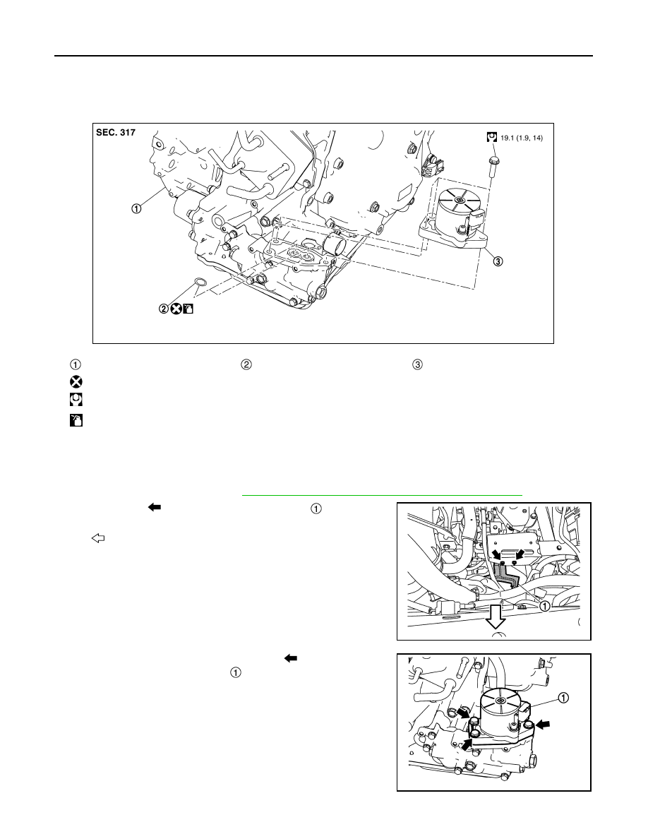
Exploded View
INFOID:0000000010742044
Removal and Installation
INFOID:0000000010742045
REMOVAL
1.
Remove the battery tray. Refer to
PG-148, "EXCEPT FOR R9M : Removal and Installation"
2.
Remove nuts (
) and remove harness bracket
.
3.
Disconnect the electric oil pump harness connector.
4.
Remove electric oil pump mounting bolts (
) and remove elec-
tric oil pump & motor assembly
.
Transaxle assembly
O-ring
Electric oil pump & motor assembly
: Always replace after every disassembly.
: N·m (kg-m, ft-lb)
: Apply CVT fluid
JSDIA5137GB
: Vehicle front
JSDIA6395ZZ
JSDIA5215ZZ