содержание .. 2183 2184 2185 2186 ..
Nissan X-Trail 32. Manual - part 2185
TM-698
< REMOVAL AND INSTALLATION >
[CVT: RE0F10G]
CVT FLUID COOLER SYSTEM
Inspection and Adjustment
INFOID:0000000010622912
INSPECTION AFTER INSTALLATION
Start the engine and check visually that there is no leakage of CVT fluid.
ADJUSTMENT AFTER INSTALLATION
Adjust the CVT fluid level. Refer to
.
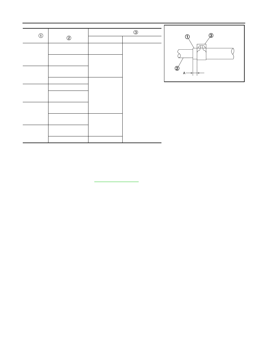
Hose
Installation side tube
Hose clamp
Direction of tab
Clamping position (A)
Fluid cooler
hose B
CVT fluid cooler tube
A
Frontward
5 – 9 mm (0.20 – 0.35
in) from hose end
Fluid cooler tube as-
sembly
Leftward
Fluid cooler
hose C
Fluid cooler tube as-
sembly
CVT fluid cooler
Frontward
Fluid cooler
hose D
CVT fluid cooler
Fluid cooler bracket
(with tube)
Fluid cooler
hose E
Fluid cooler bracket
(with tube)
Fluid cooler tube as-
sembly
Leftward
Fluid cooler
hose F
Fluid cooler tube as-
sembly
CVT oil warmer
Upward
JSDIA2424ZZ