содержание .. 2179 2180 2181 2182 ..
Nissan X-Trail 32. Manual - part 2181
TM-682
< REMOVAL AND INSTALLATION >
[CVT: RE0F10G]
OIL PAN
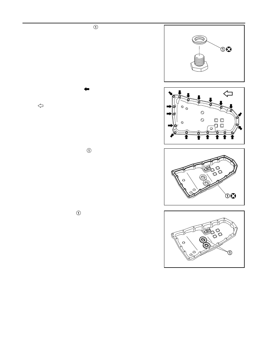
3.
Remove the drain plug gasket
.
4.
Remove the oil pan bolts (
) and remove the oil pan and oil pan
gasket.
5.
Remove the oil pan gasket
from the oil pan.
6.
Remove the magnets
from the oil pan.
INSTALLATION
Note the followings and installation is in the reverse order of removal.
CAUTION:
• Never reuse oil pan gasket.
• Never reuse drain plug gasket.
• Completely clean the iron powder from the magnet area of oil pan and the magnets.
• Install the oil pan to the transaxle case with the following procedure.
1.
Install the oil pan gasket to the oil pan.
CAUTION:
Completely wipe out any moisture, oil, and old gasket from the oil pan gasket surface and bolt
hole of oil pan and transaxle case.
2.
Install the oil pan assembly to the transaxle case and temporarily tighten the oil pan bolt.
JSDIA5206ZZ
: Vehicle front
JSDIA5207ZZ
JSDIA5208ZZ
JSDIA5209ZZ