содержание .. 2177 2178 2179 2180 ..
Nissan X-Trail 32. Manual - part 2179
TM-674
< REMOVAL AND INSTALLATION >
[CVT: RE0F10G]
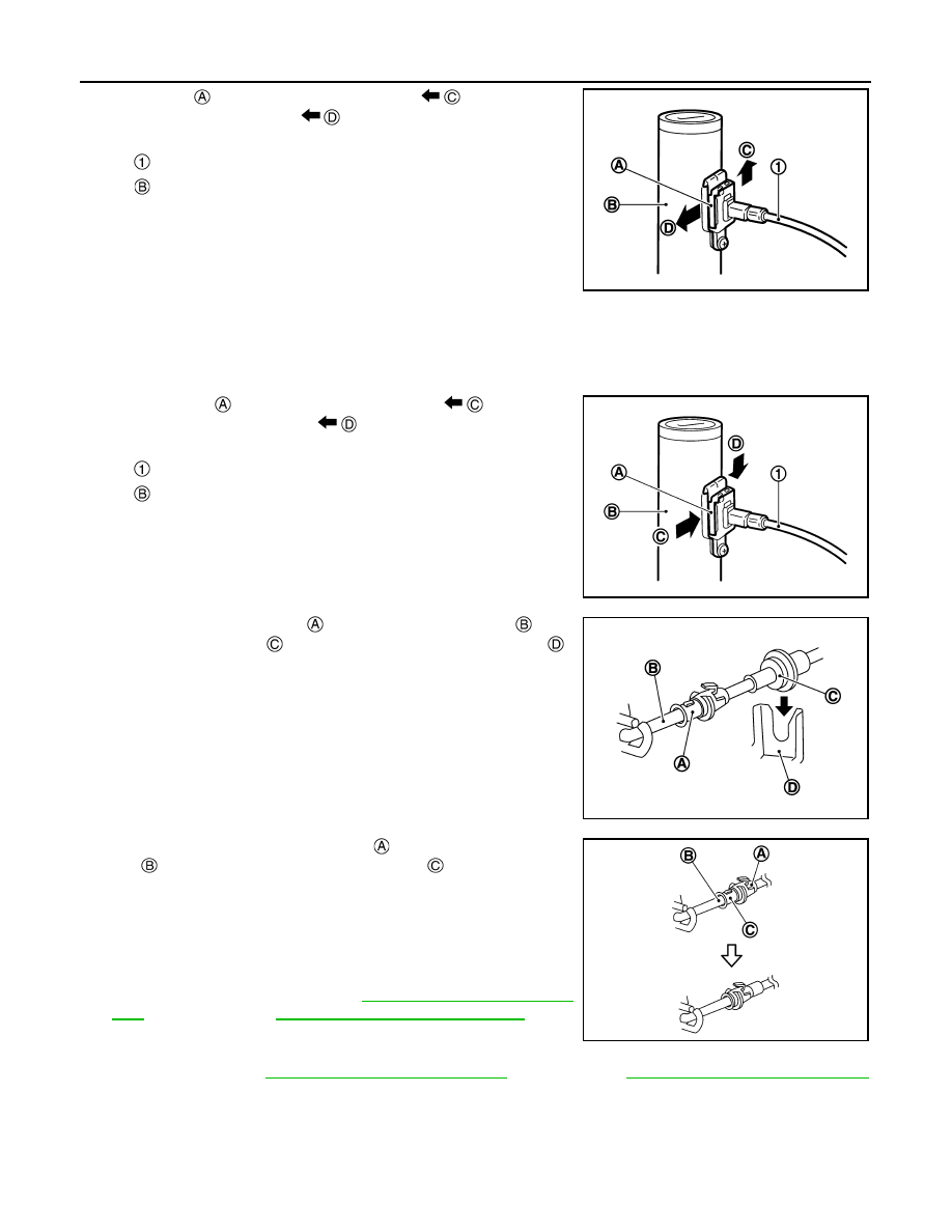
KEY INTERLOCK CABLE
5.
Lift the clip
in the direction of the arrow (
) and remove in
the direction of the arrow (
).
6.
Remove the key interlock cable from the key cylinder.
7.
Disengage the clip and disconnect the key interlock cable from
the vehicle.
INSTALLATION
1.
Move the shift selector to "P" position.
2.
Turn the ignition switch to ACC or ON position.
3.
Install the holder of key interlock cable to key cylinder.
4.
Install the clip
in the direction of the arrow (
) and push it
in the direction of the arrow (
).
5.
Turn the ignition switch to LOCK position.
6.
Install the adjusting holder
onto the key interlock rod
, then
install the casing cap
onto the shift selector cable bracket
.
CAUTION:
• When installing the key interlock cable, do not bend or
twist the cable forcefully.
• After connecting the key interlock cable to the shift selec-
tor cable bracket, be sure to check that the casing cap is
completely fastened to the cable bracket. If the casing cap
is easily displaced, replace the key interlock cable.
7.
Slide the key interlock cable slider
toward the key interlock
rod
side and install the adjusting holder
and key interlock
rod.
CAUTION:
• Never squeeze the pawls on the key interlock cable slider
when holding the slider.
• Never apply force in a perpendicular direction to the key
interlock rod when sliding the slider.
8.
Install the center console. Refer to
(LHD models),
IP-52, "Removal and Installation"
models).
9.
Install the instrument lower panel (driver side) and steering col-
umn cover. Refer to
IP-14, "Removal and Installation"
IP-41, "Removal and Installation"
(RHD models).
Inspection
INFOID:0000000011009352
INSPECTION AFTER INSTALLATION
: Key interlock cable
: Key cylinder
JSDIA1798ZZ
: Key interlock cable
: Key cylinder
JSDIA3589ZZ
JSDIA1799ZZ
JSDIA2644ZZ