Nissan X-Trail 32. Manual - part 2119


  Главная      Nissan     Nissan X-Trail 32 - Service Manual


поиск по сайту            


содержание   ..  2117  2118  2119  2120   ..


Nissan X-Trail 32. Manual - part 2119


TM-434

< REMOVAL AND INSTALLATION >

[CVT: RE0F10D]

WATER HOSE

CAUTION:

Perform when the engine is cold.
NOTE:
When removing components such as hoses, tubes/lines, etc., cap or plug openings to prevent fluid from spill-
ing.
1.

Remove battery tray. Refer to 

PG-148, "EXCEPT FOR R9M : Removal and Installation"

.

2.

Remove engine under cover. Refer to 

EXT-40, "ENGINE UNDER COVER : Removal and Installation"

.

3.

Remove CVT fluid charging pipe. Refer to 

TM-449, "Exploded View"

4.

Remove splash side cover LH. Refer to 

EXT-35, "FENDER PROTECTOR : Exploded View"

.

5.

Remove water hose A, B, C, and heater thermostat.

INSTALLATION

Note the followings and installation is in the reverse order of removal.

CAUTION:

• Never reuse hose clamps.
• Never reuse hose clip
• Securely install the water hose clip to the bracket hole of charging pipe.
• Refer to the following when installing water hoses.

• Refer to the followings when installing hose clamp.

CAUTION:

Hose clamp should not interfere with the bulge of tube.

QR25DE : Inspection

INFOID:0000000010622628

INSPECTION AFTER REMOVAL
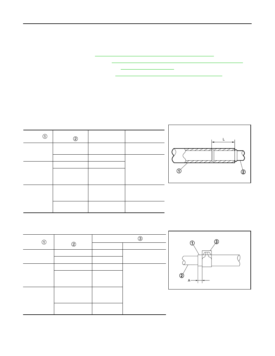
Hhose 

Installation side 

tube 

Direction of paint 

mark

Hose insertion depth 

(L)

Water hose A

Water outlet

Upward

End reaches the end 
of tube.

CVT oil warmer

Frontward

End reaches the 2-
stage bulge.

Water hose B

CVT oil warmer

Frontward

Heater thermostat

Align with the mark 
on the heater ther-
mostat

Water hose C

Heater thermostat

Align with the mark 
on the heater ther-
mostat

End reaches the ex-
pansion part.

Water outlet

Upward

End reaches the end 
of tube.

Hose 

Installation side tube 

Hose clamp 

Direction of tab

Clamping position (A)

Water hose A

Water outlet

Upward

5 – 7 mm (0.20 – 0.28 
in) from hose end

CVT oil warmer

Leftward

Water hose B

CVT oil warmer

Leftward

5 – 9 mm (0.20 – 0.35 
in) from hose end

Heater thermostat

Align with the 
mark on the 
hose

Water hose C

Heater thermostat

Align with the 
mark on the 
hose

Water outlet

Upward and 
45

°

 forward

JSDIA2459ZZ

JSDIA2424ZZ

WATER HOSE

TM-435

< REMOVAL AND INSTALLATION >

[CVT: RE0F10D]

C

E

F

G

H

I

J

K

L

M

A

B

TM

N

O

P

Heater Thermostat

1.

Fully immerse the heater thermostat 

 in a container (A) filled

with water. Continue heating the water while stirring.

2.

Continue heating the heater thermostat for 5 minutes or more
after bringing the water to a boil.

3.

Quickly take the heater thermostat out of the hot water, measure the heater thermostat within 10 seconds.

-

Place dial indicator (A) on the pellet 

 and measure the elonga-

tion from the initial state.

4.

If out of standard, replace heater thermostat.

INSPECTION AFTER INSTALLATION

Start the engine and check visually that there is no leakage of engine coolant.

JSDIA3661ZZ

Standard

: Refer to 

TM-457, "Heater Thermostat"

.

JSDIA3662ZZ

TM-436

< REMOVAL AND INSTALLATION >

[CVT: RE0F10D]

CVT FLUID COOLER SYSTEM

CVT FLUID COOLER SYSTEM

MR20DD

MR20DD : Exploded View

INFOID:0000000010622629

Transaxle side

Vehicle side

JSDIA5320GB

Transaxle assembly

Copper washer

Fluid cooler tube A

Fluid cooler tube B 

Hose clamp

Fluid cooler hose A

CVT oil warmer

: Always replace after every disassembly.

: N·m (kg-m, ft-lb)

JSDIA6022GB

CVT FLUID COOLER SYSTEM

TM-437

< REMOVAL AND INSTALLATION >

[CVT: RE0F10D]

C

E

F

G

H

I

J

K

L

M

A

B

TM

N

O

P

MR20DD : Removal and Installation

INFOID:0000000010622630

REMOVAL

NOTE:
When removing components such as hoses, tubes/lines, etc., cap or plug openings to prevent fluid from spill-
ing.

1.

Remove front bumper. Refer to 

EXT-15, "Removal and Installation"

.

2.

Pull out fluid cooler hose C 

 and fluid cooler hose E 

 from

fluid cooler tube assembly.

3.

Remove the mounting bolts (

) of fluid cooler tube assembly

.

4.

Pull out fluid cooler hose F 

 and fluid cooler hose B 

 from

fluid cooler tube assembly.

5.

Remove CVT fluid cooler mounting bolts 

 and mounting nuts

 and take out the CVT fluid cooler.

CAUTION:

Be careful not to damage the radiator fins while taking out
the CVT fluid cooler.

Bracket

Bumper reinforcement

Fluid cooler hose D

Hose clamp

Fluid cooler bracket (with tube)

CVT fluid cooler 

Bracket

Fluid cooler hose C

Fluid cooler hose E

Fluid cooler tube assembly

Fluid cooler hose F

Fluid cooler hose B

Fluid cooler tube A

CVT oil warmer

Transaxle assembly

Bumper reinforcement lower

: Always replace after every disassembly.

: N·m (kg-m, in-lb)

: Hose clamp

: Vehicle front

JSDIA5376ZZ

: Hose clamp

JSDIA6136ZZ

: Vehicle front

JSDIA5378ZZ


содержание   ..  2117  2118  2119  2120   ..