Nissan X-Trail 32. Manual - part 2118


  Главная      Nissan     Nissan X-Trail 32 - Service Manual


поиск по сайту            


содержание   ..  2116  2117  2118  2119   ..


Nissan X-Trail 32. Manual - part 2118


TM-430

< REMOVAL AND INSTALLATION >

[CVT: RE0F10D]

DIFFERENTIAL SIDE OIL SEAL

2.

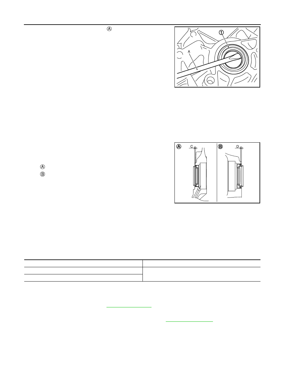
Remove differential side oil seal 

 using oil seal remover (A)

(commercial service tool).

CAUTION:

Be careful not to scratch transaxle case and converter
housing.

INSTALLATION

Note the followings and installation is in the reverse order of removal.

CAUTION:

• Never reuse differential side oil seal.
• Apply CVT fluid to differential side oil seals.
• When inserting the drive shaft, be sure to use Tool.

Install each differential side oil seal evenly using suitable tool so that
differential side oil seal protrudes by the dimension (C) and (D)
respectfully.

NOTE:

The reference is the installation direction of the differential side oil seal.

Drift to be used:

Inspection and Adjustment

INFOID:0000000010622622

INSPECTION AFTER INSTALLATION

Check for CVT fluid leakage. Refer to 

TM-399, "Inspection"

.

ADJUSTMENT AFTER INSTALLATION

If CVT fluid leaks during work, adjust the CVT fluid level. Refer to 

TM-401, "Adjustment"

.

JPDIA0118ZZ

Tool number

: KV38107900

: Differential side oil seal (LH)

: Differential side oil seal (RH) (2WD models only)

JPDIA0520ZZ

Dimension (C)

:Height difference from case end surface is within 1.8 

±

 0.5 mm (0.071 

±


0.020 in).

Dimension (D)

:Height difference from case end surface is within 2.2 

±

 0.5 mm (0.087 

±


0.020 in).

Location

Commercial Service Tools

Transaxle case side

Commercial service tool with outer dia. 56 mm (2.20 in) and in-
ner dia. 50 mm (1.97 in)

Converter housing side

WATER HOSE

TM-431

< REMOVAL AND INSTALLATION >

[CVT: RE0F10D]

C

E

F

G

H

I

J

K

L

M

A

B

TM

N

O

P

WATER HOSE

MR20DD

MR20DD : Exploded View

INFOID:0000000010622623

MR20DD : Removal and Installation

INFOID:0000000010622624

REMOVAL

WARNING:

Never remove the radiator cap when the engine is hot. Serious burns could occur from high pressure
coolant escaping from the radiator. Wrap a thick cloth around the cap. Slowly turn it a quarter turn to
allow built-up pressure to escape. Carefully remove the cap by turning it all the way.

CAUTION:

Perform when the engine is cold.
NOTE:
When removing components such as hoses, tubes/lines, etc., cap or plug openings to prevent fluid from spill-
ing.

1.

Remove air duct 1. Refer to 

EM-30, "Exploded View"

.

2.

Remove water hose and heater thermostat assembly.

INSTALLATION

Note the followings and installation is in the reverse order of removal.

CAUTION:

• Never reuse hose clamps.

Water outlet

Transaxle assembly

Heater thermostat assembly

Hose clamp

CVT oil warmer

Water hose

To thermostat housing

To engine oil cooler

: Always replace after every disassembly.

: N·m (kg-m, ft-lb)

JSDIA5317GB

TM-432

< REMOVAL AND INSTALLATION >

[CVT: RE0F10D]

WATER HOSE

• Securely install the water hose clip to the converter housing.
• Refer to the following when installing water hoses.

• Refer to the followings when installing hose clamp.

CAUTION:

Hose clamp should not interfere with the bulge of tube.

MR20DD : Inspection

INFOID:0000000010622625

INSPECTION AFTER REMOVAL

Heater Thermostat

1.

Fully immerse the heater thermostat 

 in a container (A) filled

with water. Continue heating the water while stirring.

2.

Continue heating the heater thermostat for 5 minutes or more
after bringing the water to a boil.

3.

Quickly take the heater thermostat out of the hot water, measure the heater thermostat within 10 seconds.

Hose 

Installation side tube 

Direction of paint mark

Hose insertion depth (L)

Heater thermostat assembly

CVT oil warmer

Frontward

Hose end reaches the 2-stage 
bulge.

Water hose

CVT oil warmer

Frontward

Water outlet

Frontward

Hose end reaches the end of 
tube.

JSDIA3579ZZ

Hose 

Installation side tube 

Hose clamp 

Direction of tab

Clamping position (A)

Heater thermo-
stat assembly

CVT oil warmer

Frontward

5 – 9 mm (0.20 – 0.35 in) 
from hose end

Water hose

CVT oil warmer

Upward and 
30

°

 frontward

5 – 7 mm (0.20 – 0.28 in) 
from hose end

Water outlet

Frontward

JSDIA2424ZZ

JSDIA3661ZZ

WATER HOSE

TM-433

< REMOVAL AND INSTALLATION >

[CVT: RE0F10D]

C

E

F

G

H

I

J

K

L

M

A

B

TM

N

O

P

-

Place dial indicator (A) on the pellet 

 and measure the elonga-

tion from the initial state.

4.

If out of standard, replace heater thermostat.

INSPECTION AFTER INSTALLATION

Start the engine and check visually that there is no leakage of engine coolant.

QR25DE

QR25DE : Exploded View

INFOID:0000000010622626

QR25DE : Removal and Installation

INFOID:0000000010622627

REMOVAL

WARNING:

Never remove the radiator cap when the engine is hot. Serious burns could occur from high pressure
engine coolant escaping from the radiator. Wrap a thick cloth around the cap. Slowly turn it a quarter
turn to allow built-up pressure to escape. Carefully remove the cap by turning it all the way.    

Standard

: Refer to 

TM-457, "Heater Thermostat"

.

JSDIA3662ZZ

Water outlet

Hose clamp

Water hose A

Clip

CVT oil warmer

Transaxle assembly

Water hose B

Heater thermostat

Water hose C

: Always replace after every disassembly.

: N·m (kg-m, ft-lb)

JSDIA5142GB


содержание   ..  2116  2117  2118  2119   ..