содержание .. 2074 2075 2076 2077 ..
Nissan X-Trail 32. Manual - part 2076
TM-262
< SYSTEM DESCRIPTION >
[CVT: RE0F10D]
SYSTEM
REVERSE PROHIBIT CONTROL
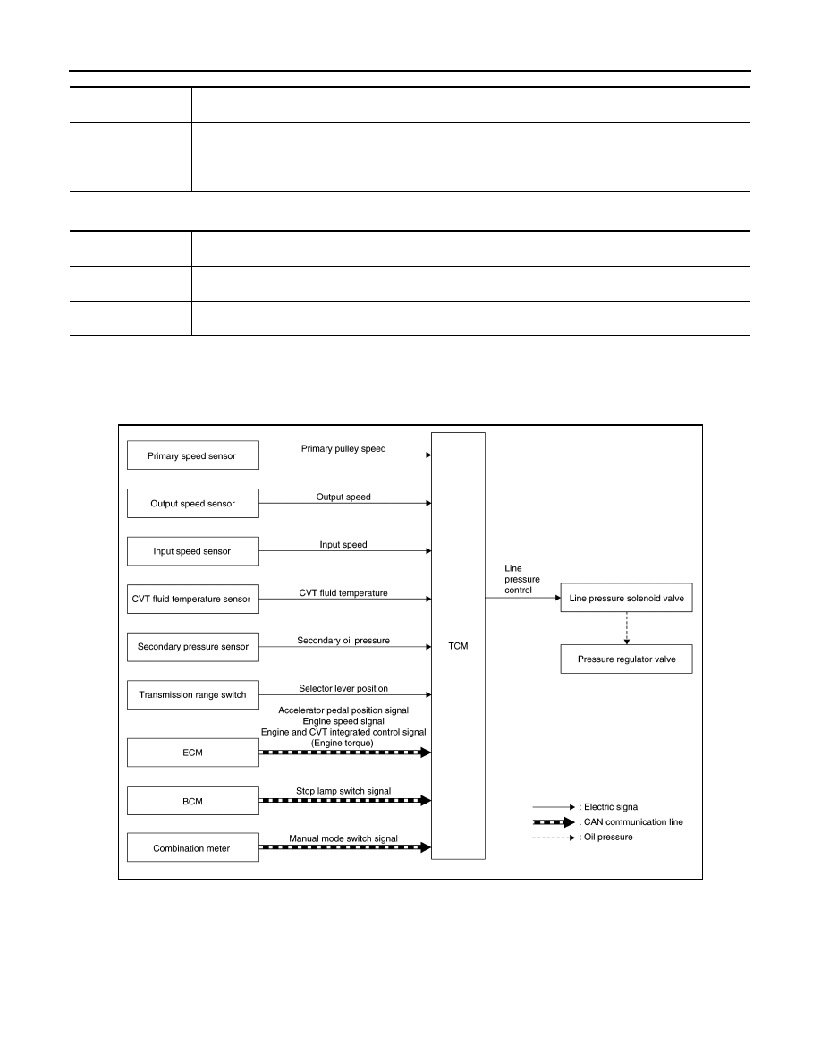
LINE PRESSURE CONTROL
LINE PRESSURE CONTROL : System Description
INFOID:0000000010622455
SYSTEM DIAGRAM
DESCRIPTION
Highly accurate line pressure control and secondary pressure control reduces friction for improvement of fuel
economy.
Normal Oil Pressure Control
Appropriate line pressure and secondary pressure suitable for driving condition are determined based on the
accelerator pedal position, engine speed, primary pulley (input) speed, secondary pulley (output) speed, vehi-
cle speed, input torque, stop lamp switch signal, transmission range switch signal, lock-up signal, power volt-
age, target shift ratio, oil temperature, oil pressure, and manual mode switch signal.
Control
When the CVT fluid temperature is high, the gear shift permission maximum revolution and the maximum
torque are reduced than usual to prevent increase of the oil temperature.
Vehicle behavior in
control
Power performance may be lowered, compared to normal control.
Normal return condi-
tion
The control returns to the normal control when CVT fluid temperature is lowered.
Control
The reverse brake is controlled to avoid becoming engaged when the selector lever is set in “R” position while
driving in forward direction at more than the specified speed.
Vehicle behavior in
control
If the selector lever is put at “R” position when driving with the forward gear, the gear becomes neutral, not
reverse.
Normal return condi-
tion
The control returns to normal control when the vehicle is driven at low speeds. (The reverse brake becomes
engaged.)
JSDIA5312GB