Nissan X-Trail 32. Manual - part 2019


  Главная      Nissan     Nissan X-Trail 32 - Service Manual


поиск по сайту            


содержание   ..  2017  2018  2019  2020   ..


Nissan X-Trail 32. Manual - part 2019


TM-34

< REMOVAL AND INSTALLATION >

[6MT: RS6F94R]

CONTROL LINKAGE

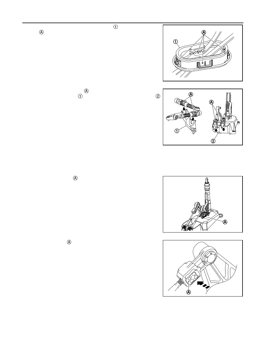
• From under the vehicle, press grommet 

 into place until the

pawls  

securely.

CAUTION:

Check that pulling down on the grommet does not fall out it.

• Insert the each socket part 

 of cable until it reaches the cable

mounting bracket (M/T) 

 and M/T shift selector assembly 

securely.

CAUTION:

Check that pulling up on the socket does not disconnect it.

• Install select cable (M/T shift selector assembly side), as per the following procedure.

When M/T shift selector assembly is replaced with new one:

1.

Install the select cable to the M/T shift selector assembly.

2.

Shift the shift lever to the neutral position.

3.

Install the lock pin 

 to the M/T shift selector assembly as

shown in the figure.

CAUTION:

Select cable cannot be adjusted accurately without using
the lock pin.

4.

Check that shift lever does not move in the direction of the
select. If it moves, re-install lock pin.

5.

Push the stopper 

 until it reaches the select cable.

6.

Remove the lock pin from M/T shift selector assembly.

7.

Shift shift lever to each gear position to check that there are no
bindings. If any, re-install select cable with lock pin.

When M/T shift selector assembly is reused or without lock pin:

1.

Install the select cable to the M/T shift selector assembly.

2.

Shift the shift lever to the 4th gear position.

JPDIC0844ZZ

JSDIA5773ZZ

JSDIA5774ZZ

JSDIA5775ZZ

CONTROL LINKAGE

TM-35

< REMOVAL AND INSTALLATION >

[6MT: RS6F94R]

C

E

F

G

H

I

J

K

L

M

A

B

TM

N

O

P

3.

Adjust the clearance (C) between the stopper 

 and the lever 

to the standard value.

4.

Push the stopper 

 until it reaches the select cable.

5.

Shift shift lever to each gear position to check that there are no
bindings. If any, re-install select cable and re-adjust the clear-
ance.

• Perform inspection after installation. Refer to 

TM-35, "Inspection"

.

Inspection

INFOID:0000000010842450

INSPECTION AFTER INSTALLATION

• When the shift lever is shifted to each position, check that the shift lever moves smoothly (no-hook up, no-

noise, no-backlash and non-contact to other parts). If any malfunction is detected, repair the malfunctioning
parts or replace cable assembly.

• When the shift lever is shifted to reverse gear side and 5th-6th side, confirm the shift lever returns to neutral

position. When the shift lever does not return to the neutral position smoothly, check M/T shift selector
assembly and select cable condition. If any malfunction is detected, repair or replace the malfunctioning
part.

Clearance

: 3.8 – 4.0 mm (0.150 – 0.157 in)

JSDIA6477ZZ

JSDIA5775ZZ

TM-36

< REMOVAL AND INSTALLATION >

[6MT: RS6F94R]

POSITION SWITCH

POSITION SWITCH

Exploded View

INFOID:0000000010842451

Removal and Installation

INFOID:0000000010842452

REMOVAL

1.

Remove battery and battery trays. Refer to 

PG-148, "EXCEPT FOR R9M : Removal and Installation"

.

2.

Disconnect position switch harness connector.

3.

Remove position switch 

.

4.

Perform inspection after removal. Refer to 

TM-37, "Inspection"

.

INSTALLATION

1.

Apply recommended sealant to threads of position switch 

.

• For sealant to use, refer to 

TM-36, "Exploded View"

.

CAUTION:

Remove old sealant and oil adhering to threads.

Position switch

Transaxle assembly

: Vehicle front

: N·m (kg-m, ft-lb)

: Apply Genuine Liquid Gasket, Three Bond 1215 or equivalent.

JSDIA5665GB

JSDIA5917ZZ

JSDIA5918ZZ

POSITION SWITCH

TM-37

< REMOVAL AND INSTALLATION >

[6MT: RS6F94R]

C

E

F

G

H

I

J

K

L

M

A

B

TM

N

O

P

2.

Install position switch 

.

3.

Tighten position switch to the specified torque. Refer to 

TM-36,

"Exploded View"

.

4.

For the next step and after, install in the reverse order of
removal.

5.

Perform inspection after installation. Refer to 

TM-37, "Inspec-

tion"

.

Inspection

INFOID:0000000010842453

INSPECTION AFTER REMOVAL

Check continuity between position switch terminals. Refer to 

TM-24, "Component Inspection"

.

INSPECTION AFTER INSTALLATION

Check the oil leakage. Refer to 

TM-27, "Inspection"

.

JSDIA5917ZZ


содержание   ..  2017  2018  2019  2020   ..