содержание .. 2018 2019 2020 2021 ..
Nissan X-Trail 32. Manual - part 2020
TM-38
< REMOVAL AND INSTALLATION >
[6MT: RS6F94R]
DIFFERENTIAL SIDE OIL SEAL
DIFFERENTIAL SIDE OIL SEAL
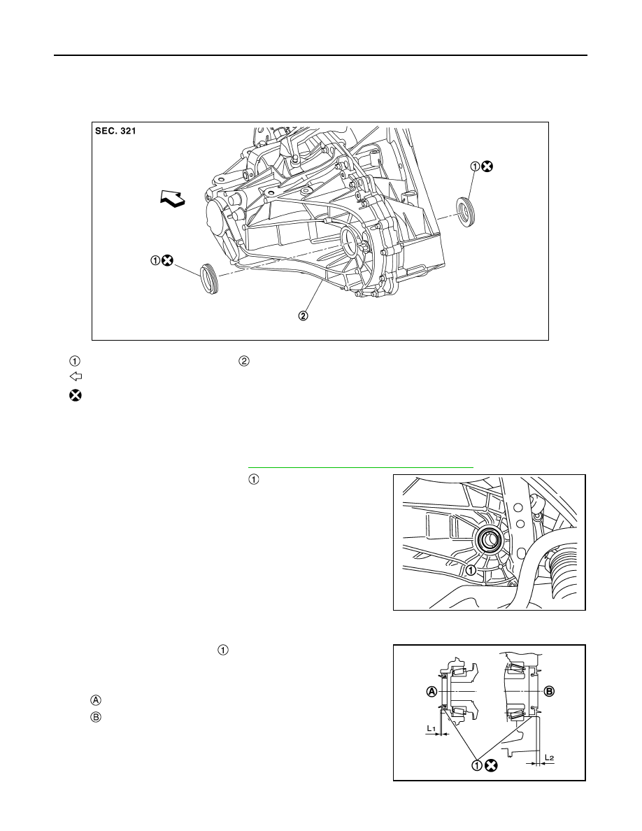
Exploded View
INFOID:0000000010842454
Removal and Installation
INFOID:0000000010842455
REMOVAL
1.
Remove front drive shafts. Refer to
FAX-36, "MR20DD : Removal and Installation"
2.
Remove differential side oil seals
from clutch housing and
transaxle case, using oil seal remover (commercial service tool).
CAUTION:
Never damage transaxle case and clutch housing.
INSTALLATION
Note the following, and install in the reverse order of removal.
• Install differential side oil seals
to clutch housing and transaxle
case, using the drift (Stamping number: B.vi 1666-B) of the drift set
(SST: KV32500QAA).
CAUTION:
• Never incline differential side oil seal.
Differential side oil seal
Transaxle assembly
: Vehicle front
: Always replace after every disassembly.
JSDIA5666ZZ
SCIA7625E
: Transaxle case side
: Clutch housing side
Dimension (L
1
)
: 1.2 – 1.8 mm (0.047 – 0.071 in)
Dimension (L
2
)
: 2.7 – 3.3 mm (0.106 – 0.130 in)
JPDIC0454ZZ