содержание .. 1953 1954 1955 1956 ..
Nissan X-Trail 32. Manual - part 1955
SR-34
< REMOVAL AND INSTALLATION >
SATELLITE SENSOR
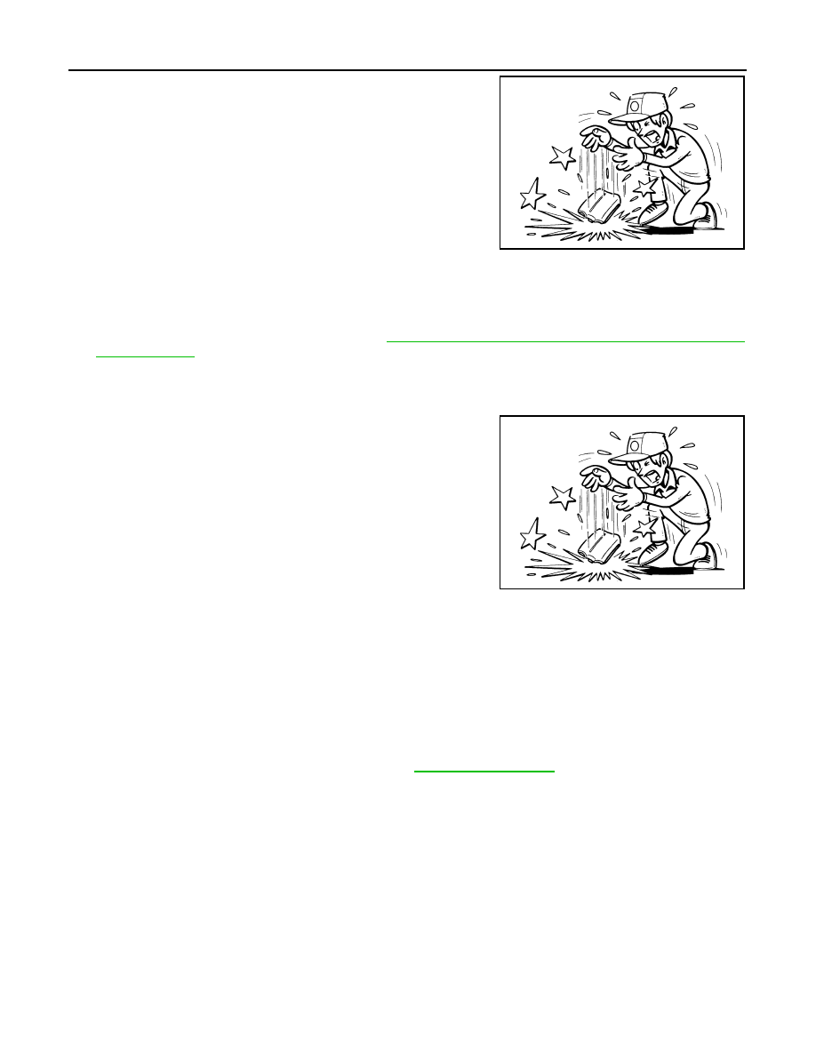
• To prevent damage to the parts, never impact the satellite
sensor.
• Replace the satellite sensor if it is dropped or sustains an
impact.
• Replace the satellite sensor of deployed side air bag module and deployed curtain air bag mod-
ule.
C-pillar Satellite Sensor
1.
Remove luggage side lower finisher. Refer to
INT-43, "LUGGAGE SIDE LOWER FINISHER : Removal
2.
Remove C-pillar satellite sensor mounting nuts.
3.
Disconnect the C-pillar satellite sensor harness connector and then remove the C-pillar satellite sensor.
CAUTION:
• To prevent damage to the parts, never impact the satellite
sensor.
• Replace the satellite sensor if it is dropped or sustains an
impact.
• Replace the satellite sensor of deployed side air bag module, deployed curtain air bag module.
INSTALLATION
Note the following items, and then install in the reverse order of removal.
CAUTION:
• Never reuse mounting nut after removal, replace with the new nut.
• Always install normally aligning to the cutout hole, because performance of the satellite sensor
excessively fluctuates according to the installation position.
• After installation is complete, perform self-diagnosis using CONSULT or air bag warning lamp, if the
system is normal and
″
PAST
″
of
″
Self Diagnostic Result
″
is indicated, always perform
″
ERASE
″
of
″
Self Diagnostic Result
″
using CONSULT. Refer to
.
• After the work is completed, check that no system malfunction is detected by air bag warning lamp.
JMHIA0009ZZ
JMHIA0009ZZ