Nissan X-Trail 32. Manual - part 1916


  Главная      Nissan     Nissan X-Trail 32 - Service Manual


поиск по сайту            


содержание   ..  1914  1915  1916  1917   ..


Nissan X-Trail 32. Manual - part 1916


SN-120

< SYSTEM DESCRIPTION >

[WITH PARK ASSIST]

COMPONENT PARTS

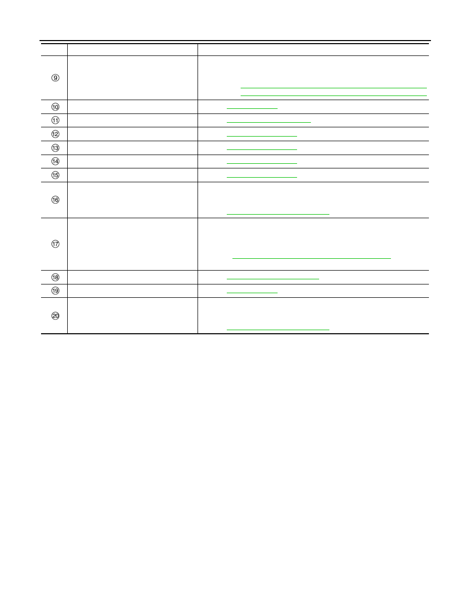
TCM
(CVT models)

Transmits the shift position signal to the sonar control unit via CAN communi-
cation.
Refer to the following, for detailed installation location.
• RE0F10D: 

TM-235, "CVT CONTROL SYSTEM : Component Parts Location"

• RE0F10G: 

TM-466, "CVT CONTROL SYSTEM : Component Parts Location"

Buzzer (backward)

Refer to 

SN-123, "Buzzer"

.

Sonar control unit

Refer to 

SN-122, "Sonar Control Unit"

.

Corner sensor rear LH

Refer to 

SN-123, "Sonar Sensor"

.

Center sensor rear LH

Refer to 

SN-123, "Sonar Sensor"

.

Center sensor rear RH

Refer to 

SN-123, "Sonar Sensor"

.

Corner sensor rear RH

Refer to 

SN-123, "Sonar Sensor"

.

NAVI control unit

When receiving a sonar indicator display signal from the sonar control unit, the 
around view monitor control unit synthesizes sonar indicator with a camera im-
age and transmits to an NAVI control unit.
Refer to 

AV-64, "Component Parts Location"

, for detailed installation location.

Combination meter

• The sonar control unit transmits the sonar indicator display signal to the com-

bination meter via CAN communication.

• The combination meter shows the sonar indicator on the information display, 

according to the signal.
Refer to 

MWI-7, "METER SYSTEM : Component Parts Location"

, for detailed 

installation location.

Sonar system switch

Refer to 

SN-122, "Sonar System Switch"

.

Buzzer (frontward)

Refer to 

SN-123, "Buzzer"

.

Around view monitor control unit

When receiving a sonar indicator display signal from the sonar control unit, the 
around view monitor control unit synthesizes sonar indicator with a camera im-
age and transmits to an NAVI control unit.
Refer to 

AV-64, "Component Parts Location"

, for detailed installation location.

No.

Component

Function

SN

COMPONENT PARTS

SN-121

< SYSTEM DESCRIPTION >

[WITH PARK ASSIST]

C

D

E

F

G

H

I

J

K

L

M

B

A

O

P

RHD MODELS

JSNIA7369ZZ

No.

Component

Function

Side sensor front RH

Refer to 

SN-123, "Sonar Sensor"

.

Corner sensor front RH

Refer to 

SN-123, "Sonar Sensor"

.

Center sensor front RH

Refer to 

SN-123, "Sonar Sensor"

.

Center sensor front LH

Refer to 

SN-123, "Sonar Sensor"

.

Corner sensor front LH

Refer to 

SN-123, "Sonar Sensor"

.

Side sensor front LH

Refer to 

SN-123, "Sonar Sensor"

.

IPDM E/R
(M/T models)

Transmits the gear position signal to the sonar control unit via CAN communi-
cation.
Refer to 

PCS-5, "Component Parts Location"

, for detailed installation location.

TCM
(CVT models)

Transmits the shift position signal to the sonar control unit via CAN communi-
cation.
Refer to the following, for detailed installation location.
• RE0F10D: 

TM-235, "CVT CONTROL SYSTEM : Component Parts Location"

• RE0F10G: 

TM-466, "CVT CONTROL SYSTEM : Component Parts Location"

ABS actuator and electric unit (control unit)

Transmits the vehicle speed signal to the sonar control unit via CAN communi-
cation.
Refer to 

BRC-14, "Component Parts Location"

, for detailed installation location.

Buzzer (backward)

Refer to 

SN-123, "Buzzer"

.

SN-122

< SYSTEM DESCRIPTION >

[WITH PARK ASSIST]

COMPONENT PARTS

Sonar Control Unit

INFOID:0000000010736628

• The warning buzzer outputs by inputting the sensor signal from

sonar sensor. The warning buzzer outputs the separated buzzer.

• The sonar indicator shows a warning according to a sensor signal

received from the sonar sensor.
NOTE:
The information display of the combination meter displays a dis-
tance between an obstacle and the sensor as well.

Sonar System Switch

INFOID:0000000010792890

• The sonar system switch is installed instrument lower panel LH

(LHD models) or instrument lower panel RH (RHD models).

• The sonar system switch signal is transmitted to the sonar control

unit.

• Non-operational status or standby status of the sonar system

(obstacle detection function) can be selected using sonar system
switch.

• Sonar system indicator lamp indicates the operation status of func-

tion.

Sonar control unit

Refer to 

SN-122, "Sonar Control Unit"

.

Corner sensor rear LH

Refer to 

SN-123, "Sonar Sensor"

.

Center sensor rear LH

Refer to 

SN-123, "Sonar Sensor"

.

Center sensor rear RH

Refer to 

SN-123, "Sonar Sensor"

.

Corner sensor rear RH

Refer to 

SN-123, "Sonar Sensor"

.

Combination meter

• The sonar control unit transmits the sonar indicator display signal to the com-

bination meter via CAN communication.

• The combination meter shows the sonar indicator on the information display, 

according to the signal.
Refer to 

MWI-7, "METER SYSTEM : Component Parts Location"

, for detailed 

installation location.

NAVI control unit

When receiving a sonar indicator display signal from the sonar control unit, the 
around view monitor control unit synthesizes sonar indicator with a camera im-
age and transmits to an NAVI control unit.
Refer to 

AV-64, "Component Parts Location"

, for detailed installation location.

Around view monitor control unit

When receiving a sonar indicator display signal from the sonar control unit, the 
around view monitor control unit synthesizes sonar indicator with a camera im-
age and transmits to an NAVI control unit.
Refer to 

AV-64, "Component Parts Location"

, for detailed installation location.

Buzzer (frontward)

Refer to 

SN-123, "Buzzer"

.

Sonar system switch

Refer to 

SN-122, "Sonar System Switch"

.

No.

Component

Function

JSNIA7370ZZ

Sonar system indicator lamp

Sonar system

ON

Standby status

OFF

Non-operational status

JSNIA7364ZZ

SN

COMPONENT PARTS

SN-123

< SYSTEM DESCRIPTION >

[WITH PARK ASSIST]

C

D

E

F

G

H

I

J

K

L

M

B

A

O

P

Sonar Sensor

INFOID:0000000010736629

When a distance from an obstacle is detected, a distance signal is
transmitted to the sonar control unit.

Buzzer

INFOID:0000000010792888

• The warning buzzer sounds with the signal from the sonar control

unit.

• Buzzer (front ward) is installed to instrument lower panel LH (LHD

models) or instrument lower panel RH (RHD models).

• Buzzer (backward) is installed inside the luggage side lower fin-

isher LH.
 

JSNIA5115ZZ

JSNIA5116ZZ


содержание   ..  1914  1915  1916  1917   ..