Nissan X-Trail 32. Manual - part 1862


  Главная      Nissan     Nissan X-Trail 32 - Service Manual


поиск по сайту            


содержание   ..  1860  1861  1862  1863   ..


Nissan X-Trail 32. Manual - part 1862


SYSTEM

SEC-215

< SYSTEM DESCRIPTION >

[WITHOUT INTELLIGENT KEY SYSTEM]

C

D

E

F

G

H

I

J

L

M

A

B

SEC

N

O

P

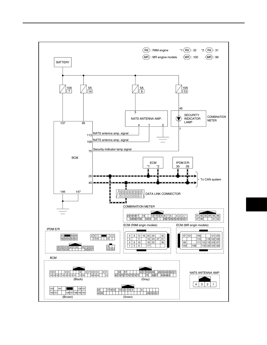
NISSAN ANTI-THEFT SYSTEM : Circuit Diagram

INFOID:0000000010922266

LHD models

JMKIB3748GB

SEC-216

< SYSTEM DESCRIPTION >

[WITHOUT INTELLIGENT KEY SYSTEM]

SYSTEM

RHD models

VEHICLE SECURITY SYSTEM

JMKIB3749GB

SYSTEM

SEC-217

< SYSTEM DESCRIPTION >

[WITHOUT INTELLIGENT KEY SYSTEM]

C

D

E

F

G

H

I

J

L

M

A

B

SEC

N

O

P

VEHICLE SECURITY SYSTEM : System Description

INFOID:0000000010926585

SYSTEM DIAGRAM

BCM INPUT/OUTPUT SIGNAL CHART

Input Signal Item

Output Signal Item

SYSTEM DESCRIPTION

JMKIB3881GB

Transmit unit

Signal name

IPDM E/R

CAN communication

Hood switch signal

Each door switch

Door switch signal

Siren control unit

Hazard warning signal

Sensor cancel switch

Sensor cancel switch signal

Reception unit

Signal name

Combination meter (security indicator lamp)

Security indicator lamp signal

Siren control unit

Alarm link signal

Hazard warning lamp

Hazard warning lamp signal

SEC-218

< SYSTEM DESCRIPTION >

[WITHOUT INTELLIGENT KEY SYSTEM]

SYSTEM

• The system reduces the possibility of a theft or mischief by sounding siren and blinking hazard warning lamp

continuously. The system activates siren and hazard warning lamp when detecting that the door or hood is
opened, or there is an illegal attempt to enter into the passenger room, while the system is in the ARMED
phase.

• Security indicator lamp on combination meter always blinks when ignition switch is any position other than

ON to warn that the vehicle is equipped with a VEHICLE SECURITY SYSTEM.

• Anti-theft function is improved by the adoption of intruder sensor that detects an attempt to enter into the

passenger room.

• Activation or deactivation of intruder sensor can be selected by sensor cancel switch.
• Siren control unit equips a built-in battery. Replace siren control unit once every 10 years because the war-

ranty for built-in battery expires after 10 years.

• Each time the system switches to the ARMED phase from the PRE-ARMED phase, the self-diagnosis is per-

formed by the siren control unit and each sensor. If any malfunction is detected, the siren sounds* 5 times to
inform the driver that a malfunction is detected and the vehicle security system does not function properly.
Malfunctioning part can be checked by “SIREN” in “ACTIVE TEST” mode of “THEFT ALM” of “BCM” using
CONSULT. Refer to 

SEC-238, "Diagnosis Description"

.

*: Siren sounds for 0.2 seconds and sound interval is 0.4 seconds.

Operation Flow

JMKIB3879GB

No.

System state

Switching condition

DISARMED to 
PRE-FULL 
ARMED

When all conditions of A and 
one condition of B is satis-
fied.

A

B

• Ignition switch: OFF
• All doors: Closed
• Hood: Closed

All doors are locked by:
• LOCK button of Keyfob

DISARMED to 
PRE-PARTIAL 
ARMED

When all conditions of A and 
one condition of B is satis-
fied.

A

B

• Ignition switch: OFF
• Hood or any door: Open

All doors are locked by:
• LOCK button of Keyfob

PRE-FULL 
ARMED to DIS-
ARMED

When one of the following 
condition is satisfied.

• Ignition switch: ON
• UNLOCK button of Keyfob: ON

PRE-PARTIAL 
ARMED to DIS-
ARMED

When one of the following 
condition is satisfied.

• Ignition switch: ON
• UNLOCK button of Keyfob: ON

PRE-PARTIAL 
ARMED to PRE-
FULL ARMED

When all of the following 
conditions are satisfied.

• All doors: Closed
• Hood: Closed

PRE-FULL 
ARMED to PRE-
PARTIAL ARMED 

When one of the following 
condition is satisfied.

• Any door: Opened
• Hood: Opened


содержание   ..  1860  1861  1862  1863   ..