содержание .. 1859 1860 1861 1862 ..
Nissan X-Trail 32. Manual - part 1861
COMPONENT PARTS
SEC-211
< SYSTEM DESCRIPTION >
[WITHOUT INTELLIGENT KEY SYSTEM]
C
D
E
F
G
H
I
J
L
M
A
B
SEC
N
O
P
SYSTEM DESCRIPTION
COMPONENT PARTS
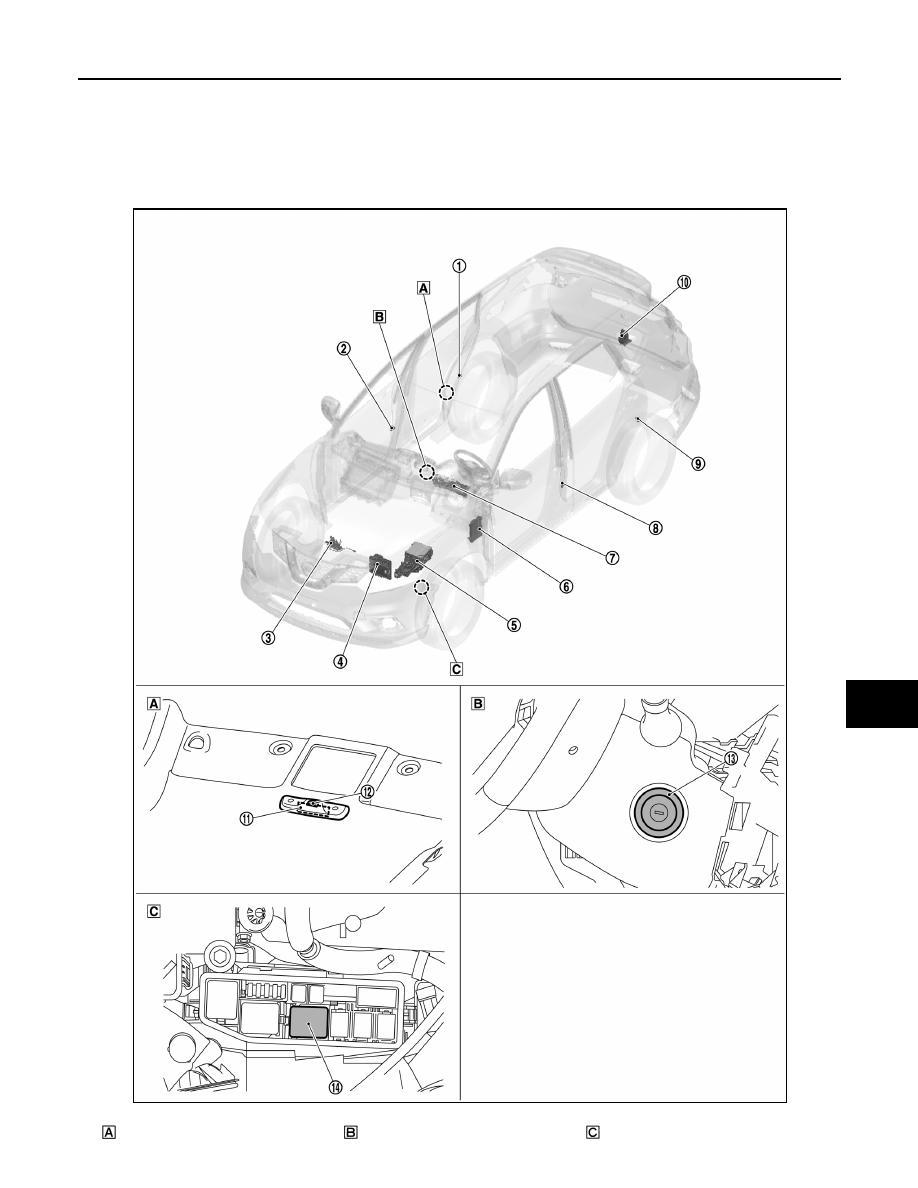
Component Parts Location
INFOID:0000000010922263
View with head lining
View with steering column
View with F/L Fuse holder No.2
JMKIB3705ZZ