Nissan X-Trail 32. Manual - part 1585


  Главная      Nissan     Nissan X-Trail 32 - Service Manual


поиск по сайту            


содержание   ..  1583  1584  1585  1586   ..


Nissan X-Trail 32. Manual - part 1585


MWI-22

< SYSTEM DESCRIPTION >

SYSTEM

TACHOMETER

TACHOMETER : System Description

INFOID:0000000010714986
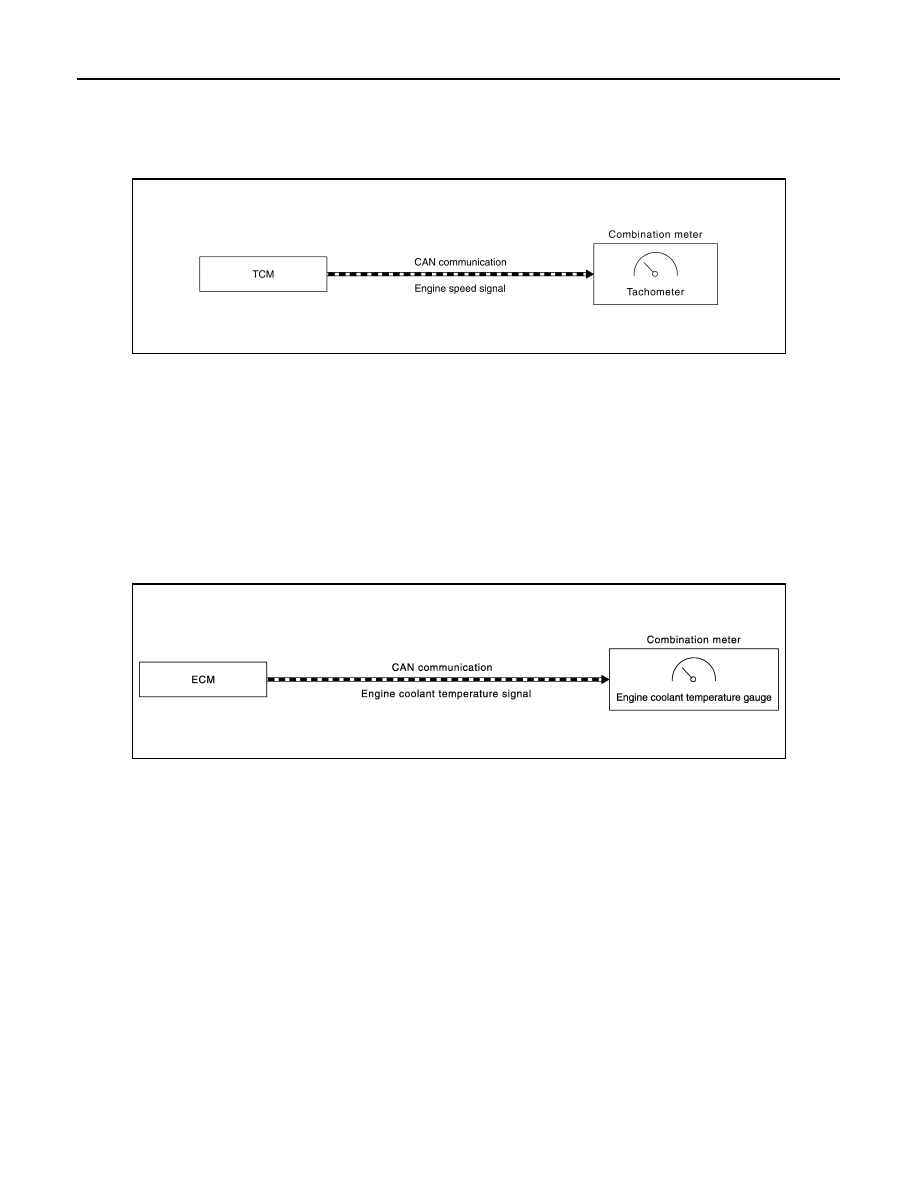
SYSTEM DIAGRAM

DESCRIPTION

• ECM converts the pulse signal provided by the crankshaft position sensor to an engine speed signal and

transmits it to the TCM via CAN communication.

• TCM transmits the engine speed signal received from ECM via CAN communication to the combination

meter via CAN communication.

• The combination meter indicates the engine speed to the tachometer according to the engine speed signal

received via CAN communication. 

ENGINE COOLANT TEMPERATURE GAUGE

ENGINE COOLANT TEMPERATURE GAUGE : System Description

INFOID:0000000010714987

SYSTEM DIAGRAM

DESCRIPTION

• ECM reads the engine coolant temperature signal from the engine coolant temperature sensor and transmits

the signal to the combination meter via CAN communication. 

• The combination meter indicates the engine coolant temperature to the engine coolant temperature gauge

according to the engine coolant temperature signal received via CAN communication. 

FUEL GAUGE

FUEL GAUGE : System Description

INFOID:0000000010714988

SYSTEM DIAGRAM

JSNIA7198GB

JSNIA3015GB

MWI

SYSTEM

MWI-23

< SYSTEM DESCRIPTION >

C

D

E

F

G

H

I

J

K

L

M

B

A

O

P

Except R9M Engine Models

R9M Engine Models

DESCRIPTION

Control Outline

The combination meter reads the fuel level sensor signal from the fuel level sensor unit and indicates the fuel
level to the fuel gauge. 

Refuel Control

The combination meter accelerates the fuel gauge if the all conditions listed below are met, or the ignition
switch is ON from OFF.
• Ignition switch is ON position.
• The vehicle is not moving.
• The fuel level change by 5   (1-1/8 Imp gal) or more.

WARNING LAMPS/INDICATOR LAMPS

WARNING LAMPS/INDICATOR LAMPS : 4WD Indicator Lamp and LOCK Indicator 
Lamp

INFOID:0000000010784392

DESIGN/PURPOSE

4WD indicator lamp and LOCK indicator lamp inform the driver for 4WD mode.
• 4WD indicator lamp

JSNIA0511GB

JSNIA7309GB

JSDIA5204ZZ

MWI-24

< SYSTEM DESCRIPTION >

SYSTEM

• LOCK indicator lamp

BULB CHECK

The 4WD indicator lamp and LOCK indicator lamp turn ON and stay ON for several seconds after turning ON
the ignition switch.

SYNCRONIZATION WITH MASTER WARNING LAMP

Not applicable

OPERATION AT COMBINATION METER CAN COMMUNICATION CUT-OFF OR UNUSUAL SIG-
NAL

For actions on CAN communications blackout in the combination meter, refer to 

MWI-19, "METER SYSTEM :

Fail-Safe"

.

SYSTEM DIAGRAM

SIGNAL PATH

• 4WD control unit receives the 4WD mode switch signal from 4WD mode switch.
• 4WD control unit transmits the 4WD mode indicator lamp signal to the combination meter via CAN communi-

cation according to the received 4WD mode switch signal.

• Combination meter turns ON the LOCK indicator lamp and/or 4WD indicator lamp when receiving the 4WD

mode indicator lamp signal.

LIGHTING AND SHUTOFF CONDITION

WARNING LAMPS/INDICATOR LAMPS : ABS Warning Lamp

INFOID:0000000010728292

DESIGN/PURPOSE

JSDIA5203ZZ

JSDIA6029GB

Condition

4WD indicator lamp

LOCK indicator lamp

Ignition switch: ON

2WD mode

OFF

OFF

AUTO mode

ON

OFF

LOCK mode

ON

ON

Ignition switch: Other than ON

OFF

OFF

MWI

SYSTEM

MWI-25

< SYSTEM DESCRIPTION >

C

D

E

F

G

H

I

J

K

L

M

B

A

O

P

The ABS warning lamp warns the driver of a malfunction in the ABS
function or EBD function of ABS actuator and electric unit (control
unit).
NOTE:
The ABS warning lamp may turn ON simultaneously with the brake
warning lamp, VDC warning lamp. For details, refer to 

BRC-30,

"System Description"

.

BULB CHECK

The ABS warning lamp turns ON and stays ON for 1 second after turning ON the ignition switch.

SYNCHRONIZATION WITH MASTER WARNING LAMP

Not applicable

OPERATION AT COMBINATION METER CAN COMMUNICATION CUT-OFF OR UNUSUAL SIG-
NAL

For actions on CAN communications blackout in the combination meter, refer to 

MWI-19, "METER SYSTEM :

Fail-Safe"

.

SYSTEM DIAGRAM

*: For DTCs that the ABS warning lamp turns ON, refer to 

BRC-84, "DTC Index"

.

SIGNAL PATH

• The ABS actuator and electric unit (control unit) transmits an ABS warning lamp signal to the combination

meter via CAN communication when detecting a malfunction.

• The combination meter turns ON the ABS warning lamp when receiving an ABS warning lamp signal.
• For the relationship between warning lamp and DTC, refer to 

BRC-84, "DTC Index"

.

LIGHTING CONDITION

The warning lamp turns ON when:
• A malfunction is detected in the ABS function or EBD function of the ABS actuator and electric unit (control

unit).

• For the relationship between warning lamp and DTC, refer to 

BRC-84, "DTC Index"

.

SHUTOFF CONDITION

• When the condition listed below is satisfied while the ignition switch ON:
- Erase DTC
• The ignition switch is in a position other than ON.

JPNIA1865ZZ

JSFIA1854GB


содержание   ..  1583  1584  1585  1586   ..