содержание .. 1584 1585 1586 1587 ..
Nissan X-Trail 32. Manual - part 1586
MWI-26
< SYSTEM DESCRIPTION >
SYSTEM
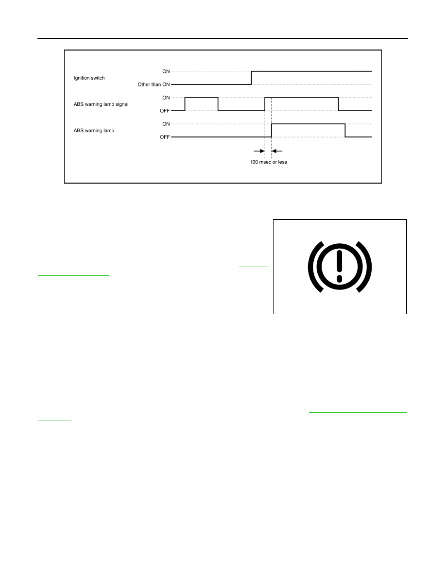
TIMING CHART
WARNING LAMPS/INDICATOR LAMPS : Brake Warning Lamp (Red)
INFOID:0000000010728294
DESIGN/PURPOSE
• The brake warning lamp warns the driver of brake fluid shortages.
• The brake warning lamp warns the driver of a malfunction in the
EBD function of ABS actuator and electric unit (control unit).
NOTE:
The brake warning lamp may turn ON simultaneously with the ABS
warning lamp, VDC warning lamp. For details, refer to
BULB CHECK
When the ignition switch is ON (engine stop).
SYNCHRONIZATION WITH MASTER WARNING LAMP
Not applicable
SYNCHRONIZATION WITH WARNING CHIME
Not applicable
OPERATION AT COMBINATION METER CAN COMMUNICATION CUT-OFF OR UNUSUAL SIG-
NAL
For actions on CAN communications blackout in the combination meter, refer to
JSFIA1752GB
JPNIA1872ZZ