Nissan X-Trail 32. Manual - part 1568


  Главная      Nissan     Nissan X-Trail 32 - Service Manual


поиск по сайту            


содержание   ..  1566  1567  1568  1569   ..


Nissan X-Trail 32. Manual - part 1568


MA-62

< PERIODIC MAINTENANCE >

CHASSIS MAINTENANCE

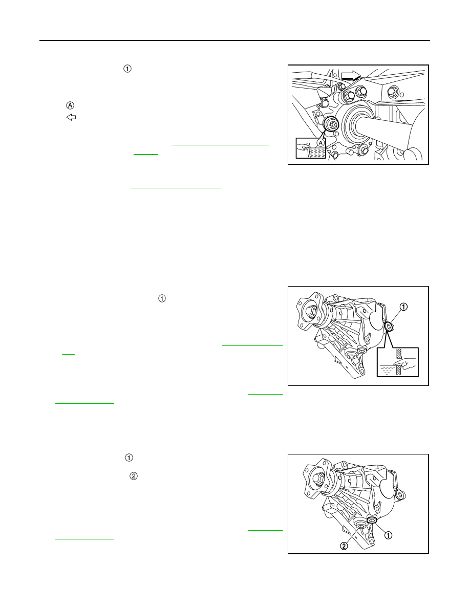
TRANSFER OIL [TY21C (QR25DE)] : Refilling

INFOID:0000000011008829

1.

Remove filler plug 

 and gasket. Then fill with new transfer oil

until oil level reaches the specified level near filler plug mounting
hole.

2.

Leave the vehicle for 3 minutes, and check the oil level again.

3.

Before installing filler plug, set a new gasket. Install filler plug to transfer assembly and tighten to the spec-
ified torque. Refer to 

DLN-83, "Exploded View"

.

CAUTION:

Never reuse gasket.

TRANSFER OIL (TY30A)

TRANSFER OIL (TY30A) : Inspection

INFOID:0000000011008830

OIL LEAKAGE

Check transfer surrounding area (oil seal, drain plug, and filler plug etc.) for oil leakage.

OIL LEVEL

1.

Check oil level from filler plug mounting hole as shown in the fig-
ure, after removing filler plug 

 and gasket from transfer assem-

bly.

CAUTION:

Turn the ignition switch OFF while checking oil level.
• Oil level should be level with bottom of filler plug mounting

hole. Add transfer oil if necessary. Refer to 

DLN-178, "Refill-

ing"

.

2.

Set a gasket on filler plug and install it on transfer assembly.

CAUTION:

Never reuse gasket.

3.

Tighten filler plug to the specified torque. Refer to 

DLN-205,

"Exploded View"

.

TRANSFER OIL (TY30A) : Draining

INFOID:0000000011008831

1.

Run the vehicle to warm up the transfer unit sufficiently.

2.

Stop the vehicle and turn the ignition switch OFF.

3.

Remove drain plug 

 and gasket.

CAUTION:

Never remove plug 

 for tooth contact test.

4.

Drain transfer oil.

5.

Set a gasket on drain plug and install it to transfer assembly.

CAUTION:

Never reuse gasket.

6.

Tighten drain plug to the specified torque. Refer to 

DLN-205,

"Exploded View"

.

: Oil level

: Vehicle front

Recommended 
oil and capacity

: Refer to 

MA-23, "Fluids and Lubri-

cants"

.

ALDIA0503ZZ

JSDIA6402ZZ

JSDIA6403ZZ

CHASSIS MAINTENANCE

MA-63

< PERIODIC MAINTENANCE >

C

D

E

F

G

H

I

J

K

L

M

B

MA

N

O

A

TRANSFER OIL (TY30A) : Refilling

INFOID:0000000011008832

1.

Fill with new transfer oil until oil level reaches the specified level

 near filler plug mounting hole, after removing filler plug 

 and

gasket from transfer assembly.

2.

Leave the vehicle for 3 minutes, and check the oil level again.

3.

Set a gasket on filler plug, and install it to transfer assembly.

CAUTION:

Never reuse gasket.

4.

Tighten filler plug to the specified torque. Refer to 

DLN-205,

"Exploded View"

.

REAR PROPELLER SHAFT

REAR PROPELLER SHAFT : Inspection

INFOID:0000000010828070

LOOSENESS OF CONNECTED PART

Check each fixing bolt and nut for looseness using torque wrench. For each tightening torque, refer to 

DLN-

214, "Exploded View"

.

BACKLASH OF JOINT PART

Move the joint of propeller shaft up and down and from side to side
(axial direction of shaft and right angle to shaft) to check that the joint
has no backlash. If the joint has a malfunction, remove propeller
shaft and perform inspection.

BACKLASH OF CENTER BEARING

Move the shaft near center bearing up and down and from side to
side (axial direction of shaft and right angle to shaft) to check that the
bearing has no backlash. If the bearing has a malfunction, remove
propeller shaft and perform inspection.

APPEARANCE AND NOISE

• Check the propeller shaft tube surface for dents or cracks. If malfunction is detected, replace propeller shaft

assembly.

• If center bearing is noisy or damaged, replace propeller shaft assembly.

VIBRATION

If vibration is present at high speed, adjust the propeller shaft phase first.

1.

Check the propeller shaft for bend and damage. If damaged, replace propeller shaft assembly.

Recommended 
oil and capacity

: Refer to 

MA-23, "Fluids and Lubri-

cants"

.

JSDIA6429ZZ

MAA0555D

MAA0005D

MA-64

< PERIODIC MAINTENANCE >

CHASSIS MAINTENANCE

2.

Perform a cruise test drive to check the propeller shaft for runout. If vibration occurs, separate propeller
shaft at final drive companion flange; then change the phase between electric controlled coupling stud bolt
and propeller shaft by the one bolt hole at a time and install propeller shaft.

3.

If vibration is still detected, measure propeller shaft runout after removing it. Refer to 

DLN-217, "Inspec-

tion"

.

REAR DIFFERENTIAL GEAR OIL

REAR DIFFERENTIAL GEAR OIL : Inspection

INFOID:0000000011008833

OIL LEAKAGE

Make sure that oil is not leaking from final drive assembly or around it.

OIL LEVEL

1.

Check oil level from filler plug mounting hole as shown in the fig-
ure after removing filler plug 

 and gasket from final drive

assembly.

CAUTION:

Turn the ignition switch OFF while checking oil level.
• Oil level should be level with bottom of filler plug mounting

hole. Add gear oil if necessary. Refer to 

DLN-227, "Refilling"

.

2.

Set a gasket on filler plug and install it on final drive assembly.

CAUTION:

Never reuse gasket.

3.

Tighten filler plug to the specified torque. Refer to 

DLN-246,

"Exploded View"

.

REAR DIFFERENTIAL GEAR OIL : Draining

INFOID:0000000011008834

1.

Turn the ignition switch OFF.

2.

Remove drain plug 

 and gasket.

3.

Drain gear oil.

4.

Set a gasket on drain plug and install it to final drive assembly.

CAUTION:

Never reuse gasket.

5.

Tighten drain plug to the specified torque. Refer to 

DLN-246,

"Exploded View"

.

REAR DIFFERENTIAL GEAR OIL : Refilling

INFOID:0000000011008835

1.

Remove filler plug 

 and gasket. Then fill with new gear oil until

oil level reaches the specified level near filler plug mounting
hole.

2.

Set a gasket on filler plug, and install it to final drive assembly.

CAUTION:

Never reuse gasket.

3.

Tighten filler plug to the specified torque. Refer to 

DLN-246,

"Exploded View"

.

WHEELS

JPDID0164ZZ

JPDID0163ZZ

Recommended 
oil and capacity

: Refer to 

MA-23, "Fluids and Lubri-

cants"

.

JPDID0164ZZ

CHASSIS MAINTENANCE

MA-65

< PERIODIC MAINTENANCE >

C

D

E

F

G

H

I

J

K

L

M

B

MA

N

O

A

WHEELS : Wheel Balance Adjustment (Aluminum Wheel)

INFOID:0000000010828074

PREPARATION BEFORE ADJUSTMENT

Using releasing agent, remove double-faced adhesive tape from the road wheel.

CAUTION:

• Never scratch the road wheel during removal.
• After removing double-faced adhesive tape, wipe clean traces of releasing agent from the road

wheel.

ADJUSTMENT

• The details of the adjustment procedure are different for each model of wheel balancer. Therefore, refer to

each instruction manual. 

• If a tire balance machine has adhesion balance weight mode settings and drive-in weight mode setting,

select and adjust a drive-in weight mode suitable for aluminum wheels.

1.

Set road wheel on tire balance machine using the center hole as a guide. Start the tire balance machine.

2.

When inner and outer unbalance values are shown on the tire balance machine indicator, multiply outer
unbalance value by 5/3 to determine balance weight that should be used. Select the outer balance weight
with a value closest to the calculated value above and install to the designated outer position of, or at the
designated angle in relation to the road wheel.

CAUTION:

• Never install the inner balance weight before installing the outer balance weight.
• Before installing the balance weight, always to clean the mating surface of the road wheel.

a.

Indicated unbalance value 

×

 5/3 = balance weight to be installed

Calculation example:
23 g (0.81 oz) 

×

 5/3 = 38.33 g (1.35 oz) 

 40 g (1.41 oz) bal-

ance weight (closer to calculated balance weight value)
NOTE:
Note that balance weight value must be closer to the calculated
balance weight value.
Example:
37.4 

 35 g (1.23 oz)

37.5 

 40 g (1.41 oz)

b.

Installed balance weight in the position.
• When installing balance weight 

 to road wheels, set it into

the grooved area 

 on the inner wall of the road wheel as

shown in the figure so that the balance weight center 

 is

aligned with the tire balance machine indication position
(angle) .

CAUTION:

• Always use genuine NISSAN balance weights.
• Balance weights are non-reusable; always replace with

new ones.

• Never install three or more sheets of balance weight.

SMA054D

JPEIC0040ZZ


содержание   ..  1566  1567  1568  1569   ..