Nissan X-Trail 32. Manual - part 1277


  Главная      Nissan     Nissan X-Trail 32 - Service Manual


поиск по сайту            


содержание   ..  1275  1276  1277  1278   ..


Nissan X-Trail 32. Manual - part 1277


FAX-100

< REMOVAL AND INSTALLATION >

[4WD]

FRONT DRIVE SHAFT

FRONT DRIVE SHAFT

MR20DD

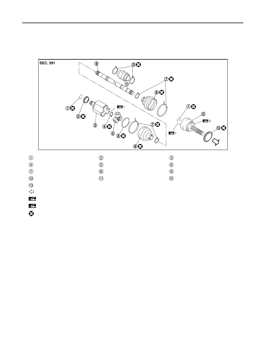
MR20DD : Exploded View

INFOID:0000000010824416

LEFT SIDE

JSDIA5389ZZ

Circular clip

Dust shield

Housing

Snap ring

Spider assembly

Stopper ring

Boot band

Boot

Shaft

Damper band

Dinamic damper

Joint sub-assembly

Dust shield

: Wheel side

1: Fill NISSAN Genuine grease or equivalent.

2: Apply paste [service parts (440037S000)].

: Always replace after every disassembly.

FRONT DRIVE SHAFT

FAX-101

< REMOVAL AND INSTALLATION >

[4WD]

C

E

F

G

H

I

J

K

L

M

A

B

FAX

N

O

P

RIGHT SIDE

MR20DD : Removal and Installation

INFOID:0000000010824417

REMOVAL

Left Side

1.

Remove tires. Refer to 

WT-61, "Removal and Installation"

.

2.

Remove wheel sensor from steering knuckle. Refer to 

BRC-212, "FRONT WHEEL SENSOR : Removal

and Installation"

.

JSDIA5460GB

Dust shield

Joint sub-assembly

Circular clip

Boot band

Boot

Shaft

Damper band

Dynamic damper

Stopper ring

Spider assembly

Snap ring

Housing

Dust shield

Support bearing

Retainer

Support bearing bracket

: Wheel side

1: Fill NISSAN Genuine grease or equivalent.

2: Apply paste [service parts (440037S000)].

: N·m (kg-m, ft-lb)

: Always replace after every disassembly.

FAX-102

< REMOVAL AND INSTALLATION >

[4WD]

FRONT DRIVE SHAFT

3.

Remove lock plate 

 from strut assembly.

• LHD: Refer to 

BR-24, "FRONT : Exploded View"

.

• RHD: Refer to 

BR-88, "FRONT : Exploded View"

.

4.

Remove caliper assembly. Hang caliper assembly in a place where it will not interfere with work.
• LHD (1 PISTON TYPE): Refer to 

BR-51, "BRAKE CALIPER ASSEMBLY (1 PISTON TYPE) : Removal

and Installation"

.

• LHD (2 PISTON TYPE): Refer to 

BR-56, "BRAKE CALIPER ASSEMBLY (2 PISTON TYPE) : Removal

and Installation"

.

• RHD (1 PISTON TYPE): Refer to 

BR-111, "BRAKE CALIPER ASSEMBLY (1 PISTON TYPE) : Removal

and Installation"

.

• RHD (2 PISTON TYPE): Refer to 

BR-116, "BRAKE CALIPER ASSEMBLY (2 PISTON TYPE) : Removal

and Installation"

.

CAUTION:

Never depress brake pedal while brake caliper is removed.

5.

Remove disc rotor. Refer to 

FAX-72, "Removal and Installation"

.

6.

Remove cotter pin, adjusting cap and then loosen wheel hub
lock nut, using a hub lock nut wrench (A) (SST: KV40104000).

7.

Patch wheel hub lock nut with a piece of wood. Hammer the
wood to disengage wheel hub and bearing assembly from drive
shaft.
NOTE:
Use suitable puller, if wheel hub and bearing assembly and drive
shaft cannot be separated even after performing the above pro-
cedure.

8.

Remove wheel hub lock nut.

9.

Remove transverse link from steering knuckle and front suspension member. Refer to 

FSU-17, "Removal

and Installation"

.

10. Separate steering outer socket from steering knuckle. Refer to 

ST-22, "Removal and Installation"

.

JSDIA3795ZZ

JSDIA2708ZZ

JPDIG0070ZZ

FRONT DRIVE SHAFT

FAX-103

< REMOVAL AND INSTALLATION >

[4WD]

C

E

F

G

H

I

J

K

L

M

A

B

FAX

N

O

P

11. Remove drive shaft from wheel hub and bearing assembly.

CAUTION:

• Never place drive shaft joint at an extreme angle. 
• Be careful not to overextend slide joint.

12. Remove drive shaft from transaxle assembly.

• Use the drive shaft attachment (A) (SST: KV40107500) and a

sliding hammer (B) (commercial service tool) while inserting
tip of the drive shaft attachment between housing and tran-
saxle assembly.

CAUTION:

• Never place drive shaft joint at an extreme angle when

removing drive shaft. Also be careful not to overextend
slide joint.

• Confirm that the circular clip is attached to the drive

shaft.

Right Side

1.

Remove tires. Refer to 

WT-61, "Removal and Installation"

.

2.

Remove wheel sensor from steering knuckle. Refer to 

BRC-212, "FRONT WHEEL SENSOR : Removal

and Installation"

.

3.

Remove lock plate 

 from strut assembly.

• LHD: Refer to 

BR-24, "FRONT : Exploded View"

.

• RHD: Refer to 

BR-88, "FRONT : Exploded View"

.

4.

Remove caliper assembly. Hang caliper assembly in a place where it will not interfere with work.
• LHD (1 PISTON TYPE): Refer to 

BR-51, "BRAKE CALIPER ASSEMBLY (1 PISTON TYPE) : Removal

and Installation"

.

• LHD (2 PISTON TYPE): Refer to 

BR-56, "BRAKE CALIPER ASSEMBLY (2 PISTON TYPE) : Removal

and Installation"

.

• RHD (1 PISTON TYPE): Refer to 

BR-111, "BRAKE CALIPER ASSEMBLY (1 PISTON TYPE) : Removal

and Installation"

.

• RHD (2 PISTON TYPE): Refer to 

BR-116, "BRAKE CALIPER ASSEMBLY (2 PISTON TYPE) : Removal

and Installation"

.

CAUTION:

Never depress brake pedal while brake caliper is removed.

5.

Remove disc rotor. Refer to 

FAX-72, "Removal and Installation"

.

JSDIA5562ZZ

JPDIF0004ZZ

JSDIA3795ZZ


содержание   ..  1275  1276  1277  1278   ..