содержание .. 1264 1265 1266 1267 ..
Nissan X-Trail 32. Manual - part 1266
FAX-56
< REMOVAL AND INSTALLATION >
[2WD]
FRONT DRIVE SHAFT
• Tighten the wheel hub lock nut to the specified torque. Refer to
CAUTION:
• Since the drive shaft is assembled by press-fitting, use the tightening torque range for the wheel
hub lock nut.
• Be sure to use torque wrench to tighten the wheel hub lock nut. Never use a power tool.
• Never reuse wheel hub lock nut.
• When installing a cotter pin
and adjusting cap
, securely bend
the basal portion to prevent rattles.
CAUTION:
Never reuse cotter pin.
• Perform inspection after installation. Refer to
R9M : Disassembly and Assembly
INFOID:0000000010824393
DISASSEMBLY
Transaxle Assembly Side
1.
Fix shaft with a vise.
CAUTION:
Protect shaft using aluminum or copper plates when fixing with a vise.
2.
Remove boot bands, and then remove boot from housing.
3.
Remove stopper ring.
4.
Put matching marks on housing and shaft, and then pull out housing from shaft.
CAUTION:
Use paint or an equivalent for matching marks. Never scratch the surfaces.
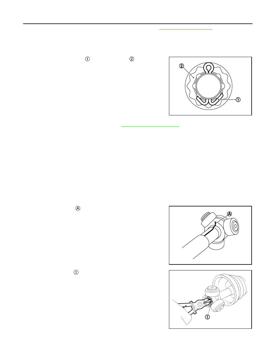
5.
Put matching marks
on the spider assembly and shaft.
CAUTION:
Use paint or an equivalent for matching marks. Never
scratch the surfaces.
6.
Remove snap ring
, and then remove spider assembly from
shaft.
7.
Remove boot from shaft.
8.
Remove circular clip from housing (left side).
9.
Remove dust shield from housing.
10. Clean old grease on housing with paper waste.
Support Bearing
JPDIF0295ZZ
JPDIF0006ZZ
JPDIF0014ZZ