содержание .. 1263 1264 1265 1266 ..
Nissan X-Trail 32. Manual - part 1265
FAX-52
< REMOVAL AND INSTALLATION >
[2WD]
FRONT DRIVE SHAFT
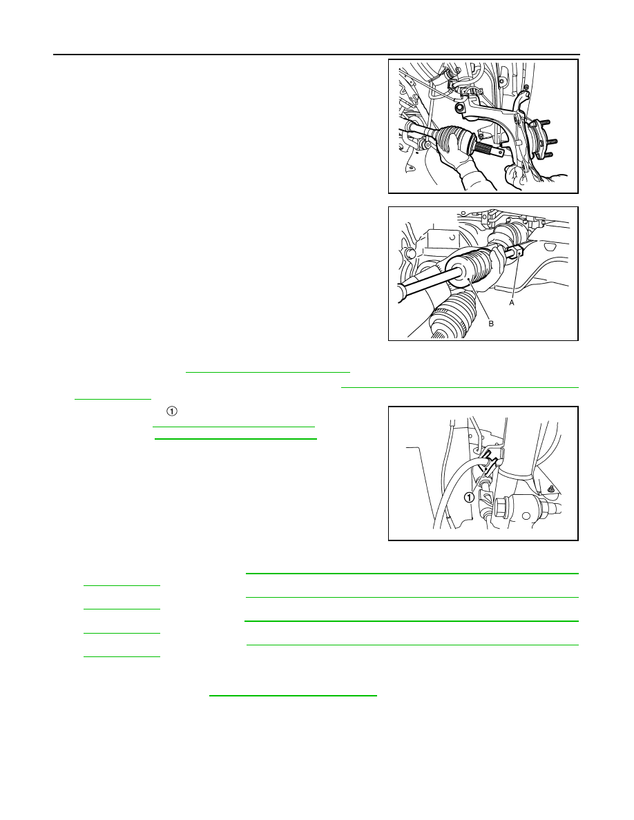
11. Remove drive shaft from wheel hub and bearing assembly.
CAUTION:
• Never place drive shaft joint at an extreme angle.
• Be careful not to overextend slide joint.
12. Remove drive shaft from transaxle assembly.
• Use the drive shaft attachment (A) (SST: KV40107500) and a
sliding hammer (B) (commercial service tool) while inserting
tip of the drive shaft attachment between housing and tran-
saxle assembly.
CAUTION:
• Never place drive shaft joint at an extreme angle when
removing drive shaft. Also be careful not to overextend
slide joint.
• Confirm that the circular clip is attached to the drive
shaft.
Right Side
1.
Remove tires. Refer to
WT-61, "Removal and Installation"
.
2.
Remove wheel sensor from steering knuckle. Refer to
BRC-212, "FRONT WHEEL SENSOR : Removal
3.
Remove lock plate
from strut assembly.
• LHD: Refer to
BR-24, "FRONT : Exploded View"
.
• RHD: Refer to
BR-88, "FRONT : Exploded View"
4.
Remove caliper assembly. Hang caliper assembly in a place where it will not interfere with work.
• LHD (1 PISTON TYPE): Refer to
BR-51, "BRAKE CALIPER ASSEMBLY (1 PISTON TYPE) : Removal
• LHD (2 PISTON TYPE): Refer to
BR-56, "BRAKE CALIPER ASSEMBLY (2 PISTON TYPE) : Removal
• RHD (1 PISTON TYPE): Refer to
BR-111, "BRAKE CALIPER ASSEMBLY (1 PISTON TYPE) : Removal
• RHD (2 PISTON TYPE): Refer to
BR-56, "BRAKE CALIPER ASSEMBLY (2 PISTON TYPE) : Removal
CAUTION:
Never depress brake pedal while brake caliper is removed.
5.
Remove disc rotor. Refer to
FAX-11, "Removal and Installation"
.
JSDIA5562ZZ
JPDIF0004ZZ
JSDIA3795ZZ