Nissan X-Trail 32. Manual - part 1267


  Главная      Nissan     Nissan X-Trail 32 - Service Manual


поиск по сайту            


содержание   ..  1265  1266  1267  1268   ..


Nissan X-Trail 32. Manual - part 1267


FAX-60

< REMOVAL AND INSTALLATION >

[2WD]

FRONT DRIVE SHAFT

4.

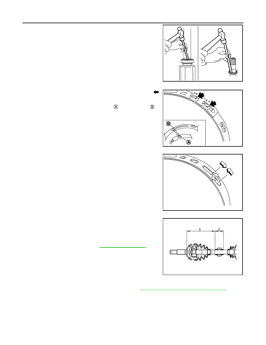
Install dust shields.

CAUTION:

Never reuse dust shields.

Dynamic Damper (If equipped)

• Put boot band in the groove on drive shaft boot. Then fit pawls (

)

into holes to temporary installation.
NOTE:
For the large diameter side, fit projection 

 and guide slit 

 at

first.

• Pinch projection on the band with suitable pliers to tighten band.
• Insert tip of band below end of the pawl.

• Secure dynamic damper with bands in the following specified posi-

tion when removing.

CAUTION:

Never reuse bands.

Wheel Side

For further details, refer to the installation procedure of “

FAX-27, "R9M : Removal and Installation"

” for the

drive shaft boot.

R9M : Inspection

INFOID:0000000010824394

INSPECTION AFTER REMOVAL

• Move joint up/down, left/right, and in the axial directions. Check for motion that is not smooth and for signifi-

cant looseness.

JPDIF0127ZZ

SDIA3557E

SDIA3558E

Demission : 

Refer 

to 

FAX-62, "Drive Shaft"

.

FAC0156D

FRONT DRIVE SHAFT

FAX-61

< REMOVAL AND INSTALLATION >

[2WD]

C

E

F

G

H

I

J

K

L

M

A

B

FAX

N

O

P

• Check boot for cracks, damage, and leakage of grease.
• Disassemble drive shaft and exchange malfunctioning part if there

is a non-standard condition.

INSPECTION AFTER DISASSEMBLY

Shaft

Check shaft for runout, cracks, or other damage. Replace if there are.

Dynamic Damper (If equipped)

Check damper for cracks or wear. Replace if necessary.

Joint Sub-Assembly (Wheel Side)

Check the following:
• Joint sub-assembly for rough rotation and excessive axial looseness
• The inside of the joint sub-assembly for entry of foreign material
• Joint sub-assembly for compression scars, cracks, and fractures inside of joint sub-assembly
Replace joint sub-assembly if there are any non-standard conditions of components.

Housing and Spider assembly (Transaxle Side)

Replace housing and spider assembly if there is scratching or wear of housing roller contact surface or spider
roller contact surface.
NOTE:
Housing and spider assembly are used in a set.

Support Bearing (Right Side)

Make sure wheel bearing rolls freely and is free from noise, cracks, pitting or wear. Replace support bearing if
there are any non-standard conditions.

Support Bearing Bracket (Right Side)

Check for bending, cracks, or damage. Replace support bearing bracket if there are any non-standard condi-
tions.

INSPECTION AFTER INSTALLATION

1.

Check wheel sensor harness for proper connection.  Refer to 

BRC-212, "FRONT WHEEL SENSOR :

Exploded View"

.

2.

Check the wheel alignment. Refer to 

FSU-8, "Inspection"

.

3.

Adjust neutral position of steering angle sensor. Refer to 

BRC-99, "Work Procedure"

.

SDIA1190J

FAX-62

< SERVICE DATA AND SPECIFICATIONS (SDS) 

[2WD]

SERVICE DATA AND SPECIFICATIONS (SDS)

SERVICE DATA AND SPECIFICATIONS (SDS)

SERVICE DATA AND SPECIFICATIONS (SDS)

Wheel Bearing

INFOID:0000000010824395

Drive Shaft

INFOID:0000000010824396

MR20DD

CVT

*: For measuring position. Refer to 

FAX-42, "MR20DD : Disassembly and Assembly"

.

M/T

*: For measuring position. Refer to 

FAX-42, "MR20DD : Disassembly and Assembly"

.

R9M

CVT

*: For measuring position. Refer to 

FAX-56, "R9M : Disassembly and Assembly"

.

M/T

Axial end play

0.05 mm (0.002 in) or less

Item

Standard

Left side

Right side

Grease quantity

Wheel side

115 – 135 g (4.06 – 4.76 oz)

Transaxle side

175 – 195 g (6.18 – 6.87 oz)

Boots installed length

*

Wheel side

141.5 mm (5.57 in)

Transaxle side

196.9 mm (7.75 in)

188.9 mm (7.44 in)

Dimension of dynamic damper

*

A

273 – 279 mm (10.75 – 10.98 in)

243 – 249 mm (9.57 – 9.80 in)

B

70 mm (2.76 in)

Item

Standard

Left side

Right side

Grease quantity

Wheel side

115 – 135 g (4.06 – 4.76 oz)

Transaxle side

175 – 195 g (6.18 – 6.87 oz)

Boots installed length

*

Wheel side

141.5 mm (5.57 in)

Transaxle side

202.1 mm (7.96 in)

188.9 mm (7.44 in)

Dimension of dynamic damper

*

A

273 – 279 mm (10.75 – 10.98 in)

243 – 249 mm (9.57 – 9.80 in)

B

70 mm (2.76 in)

Item

Standard

Left side

Right side

Grease quantity

Wheel side

145 – 165 g (5.11 – 5.82 oz)

Transaxle side

265 – 285 g (9.35 – 10.05 oz)

Boots installed length

*

Wheel side

145 mm (5.71 in)

Transaxle side

196.1 mm (7.72 in)

184.1 mm (7.25 in)

Dimension of dynamic damper

*

A

255 – 261 mm (10.04 – 10.28 in)

205 – 211 mm (8.07 – 8.31 in)

B

70 mm (2.76 in)

SERVICE DATA AND SPECIFICATIONS (SDS)

FAX-63

< SERVICE DATA AND SPECIFICATIONS (SDS) 

[2WD]

C

E

F

G

H

I

J

K

L

M

A

B

FAX

N

O

P

*: For measuring position. Refer to 

FAX-56, "R9M : Disassembly and Assembly"

.

Item

Standard

Left side

Right side

Grease quantity

Wheel side

145 – 165 g (5.11 – 5.82 oz)

Transaxle side

265 – 285 g (9.35 – 10.05 oz)

Boots installed length

*

Wheel side

145 mm (5.71 in)

Transaxle side

196.1 mm (7.72 in)

184.1 mm (7.25 in)

Dimension of dynamic damper

*

A

207 – 213 mm (8.15 – 8.39 in)

B

70 mm (2.76 in)

 —


содержание   ..  1265  1266  1267  1268   ..