содержание .. 110 111 112 113 ..
Nissan X-Trail 32. Manual - part 112
BR-42
< REMOVAL AND INSTALLATION >
[LHD]
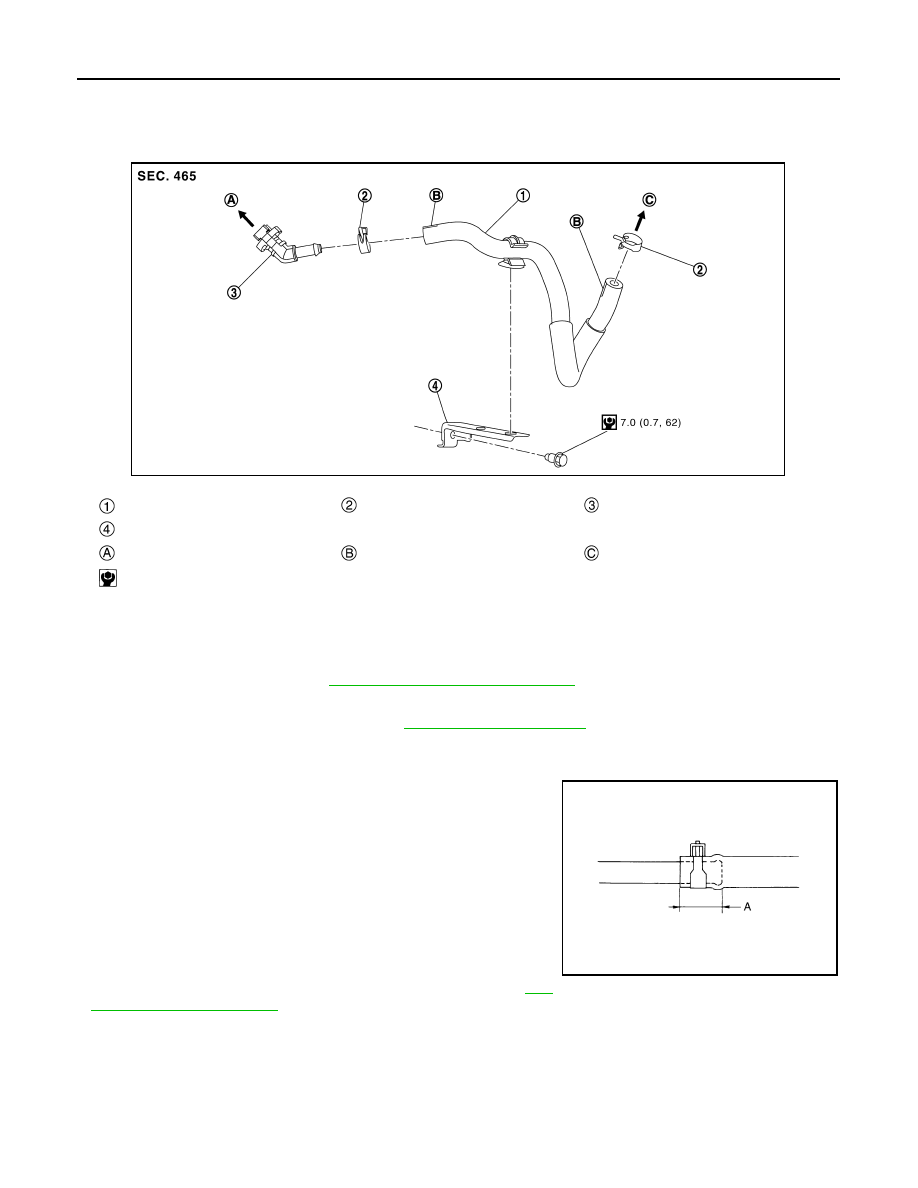
VACUUM LINES
R9M : Exploded View
INFOID:0000000010838983
R9M
R9M : Removal and Installation
INFOID:0000000010838984
REMOVAL
1.
Remove engine cover. Refer to
EM-306, "Removal and Installation"
.
2.
Remove the vacuum hose and vacuum piping.
3.
Perform inspection after removal. Refer to
INSTALLATION
Note the following, install the vacuum hose.
• When installing vacuum hose, insert it until its tip reaches the
back-end of length (A) or further as shown in the figure.
CAUTION:
Never use lubricating oil during assembly.
- Face the paint mark of vacuum hose (built-in check valve) to
upward to assemble.
- Face the paint mark of vacuum piping (intake manifold side) to
upward to assemble.
- Face the other paint marks to vehicle front side to assemble.
- For clamp mounting direction (the orientation of pawl), refer to
.
R9M : Inspection
INFOID:0000000010838985
INSPECTION AFTER REMOVAL
Appearance
Check for correct assembly, damage and deterioration.
Vacuum hose
Clamp
Connector
Vacuum hose bracket
To vacuum pump
Paint mark
To brake booster
: N·m (kg-m, in-lb)
JSFIA2547GB
A
: 24 mm (0.95 in) or more
JPFIA0023ZZ