Nissan X-Trail 32. Manual - part 111


  Главная      Nissan     Nissan X-Trail 32 - Service Manual


поиск по сайту            


содержание   ..  109  110  111  112   ..


Nissan X-Trail 32. Manual - part 111


BR-38

< REMOVAL AND INSTALLATION >

[LHD]

BRAKE BOOSTER

CAUTION:

Never reuse brake fluid to drain.

• Check each item of brake pedal. Adjust it if the measurement value is not the standard. Refer to 

BR-11,

"Inspection and Adjustment"

.

Inspection and Adjustment

INFOID:0000000010838524

INSPECTION BEFORE REMOVAL

Air Tight

CAUTION:

Check the air tight condition when the master cylinder and the brake booster is installed.

1.

Check the air tight use a handy vacuum pump.

2.

If the air tight condition cannot be maintained, perform the following operation.

a.

Check the no dirt and dust are present on the brake booster and brake master cylinder mating faces.
Clean it if necessary.

b.

Check the O-ring on the master cylinder. If anything is found, replace the O-ring. Refer to 

BR-32,

"Removal and Installation"

.

c.

Check the air tight condition again. If the condition still cannot be maintained, replace the brake booster.

INSPECTION AFTER REMOVAL

Check Valve Inspection

1.

Check the check valve to use a handy vacuum pump. 

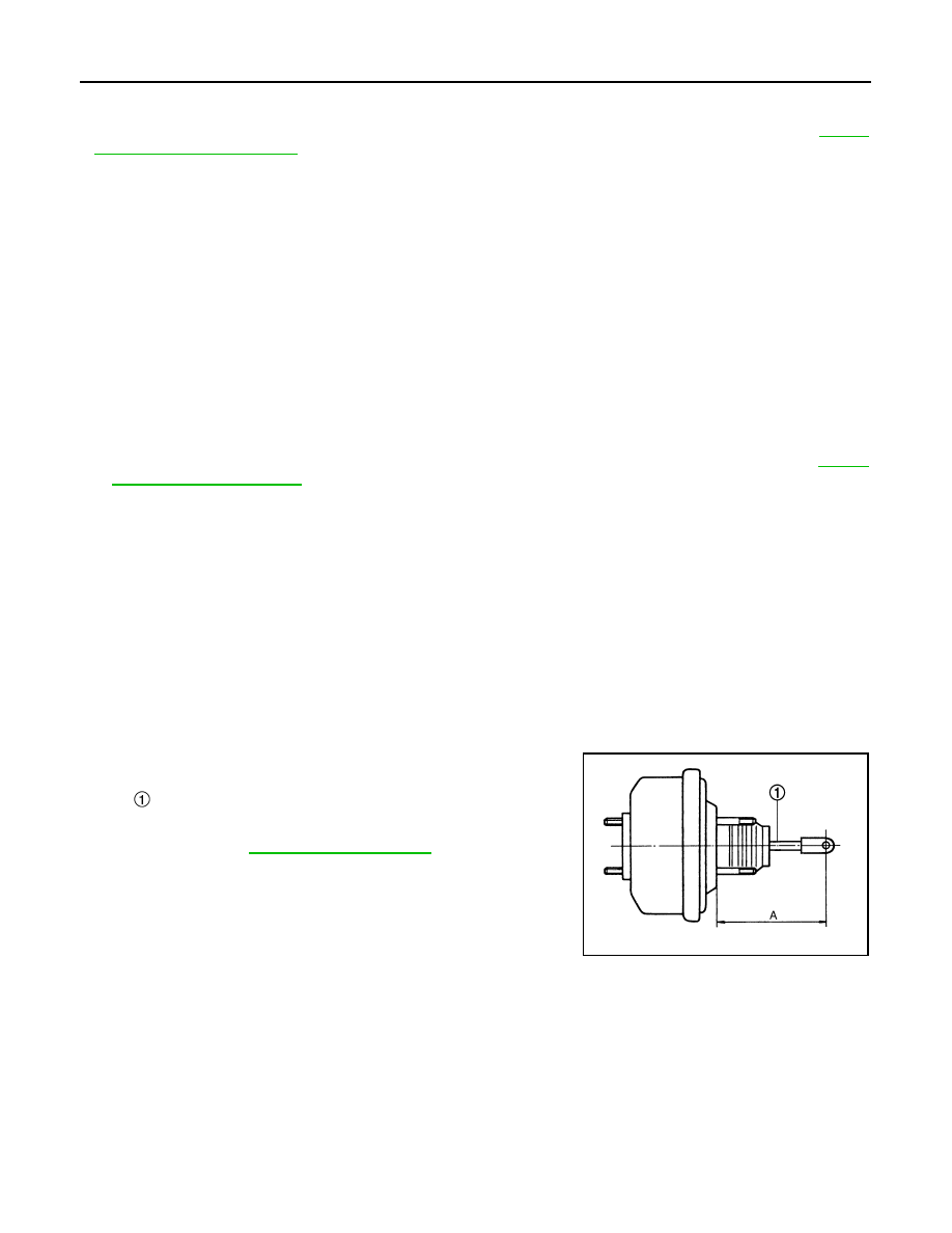
Input Rod Length rod Inspection

1.

Check the input length (A).

2.

Replace the brake booster if the input rod length is not the stan-
dard. 

INSPECTION AFTER INSTALLATION

Operation

Depress the brake pedal several times at 5-second intervals with the engine stopped. Start the engine with the
brake pedal fully depressed. Check that the clearance between brake pedal and dash lower panel decreases.
NOTE:
A slight impact with a small click may be felt on the pedal when the brake pedal is fully depressed. this is nor-
mal phenomenon due to the brake system operation.

Air Tight

1.

Run the engine at idle for 1 minute to apply vacuum to the brake booster, and stop the engine.

At vacuum of 

66.7 kPa (

500 mmHg, 

19.69 inHg, 

0.067 bar)

: Vacuum should decrease within 3.3 kPa (24.8 mmHg, 
0.98 inHg, 0.033 bar) for 15 seconds.

In the case of connecting to brake 
booster 

: Vacuum should decrease within 3.3 kPa (24.8 mmHg, 
0.98 inHg, 0.033 bar) for 15 seconds at vacuum of 

66.7 kPa (

500 mmHg, 

19.69 inHg, 

0.067 bar).

In the case of connecting to vacuum 
hose 

: Vacuum should not exist.

:Input rod

A

: Refer to 

BR-67, "Brake Booster"

JSFIA2251ZZ

BRAKE BOOSTER

BR-39

< REMOVAL AND INSTALLATION >

[LHD]

C

D

E

G

H

I

J

K

L

M

A

B

BR

N

O

P

2.

Depress the brake pedal several times at 5-second intervals until the accumulated vacuum is released to
atmospheric pressure. Check that the clearance between brake pedal and dash lower panel gradually
increases each time.

3.

Depress the brake pedal with the engine running. Then stop the engine while holding down the brake
pedal. Check that the brake pedal stroke does not change after holding down the brake pedal for 30 sec-
onds or more.

ADJUSTMENT AFTER INSTALLATION

Perform the brake pedal adjustment after installing the brake pedal assembly. Refer to 

BR-11, "Inspection and

Adjustment"

.

BR-40

< REMOVAL AND INSTALLATION >

[LHD]

VACUUM LINES

VACUUM LINES

MR20DD

MR20DD : Exploded View

INFOID:0000000010838525

MR20DD

MR20DD : Removal and Installation

INFOID:0000000010838526

REMOVAL

1.

Remove the vacuum hose and vacuum piping.

2.

Perform inspection after removal. Refer to 

BR-40, "MR20DD : Inspection"

.

INSTALLATION

Note the following, install the vacuum hose.
• When installing vacuum hose, insert it until its tip reaches the

back-end of length (A) or further as shown in the figure.

CAUTION:

Never use lubricating oil during assembly.

- Face the paint mark of vacuum hose (built-in check valve) to

upward to assemble.

- Face the paint mark of vacuum piping (intake manifold side) to

upward to assemble.

- Face the other paint marks to vehicle front side to assemble.
- For clamp mounting direction (the orientation of pawl), refer to 

BR-

40, "MR20DD : Exploded View"

.

MR20DD : Inspection

INFOID:0000000010838527

INSPECTION AFTER REMOVAL

Appearance

Check for correct assembly, damage and deterioration.

QR25DE

Vacuum piping

Vacuum hose 

Clamp

To intake manifold

Paint mark

To brake booster

JSFIA2423ZZ

A

: 24 mm (0.95 in) or more

JPFIA0023ZZ

VACUUM LINES

BR-41

< REMOVAL AND INSTALLATION >

[LHD]

C

D

E

G

H

I

J

K

L

M

A

B

BR

N

O

P

QR25DE : Exploded View

INFOID:0000000010838528

QR25DE

QR25DE : Removal and Installation

INFOID:0000000010838529

REMOVAL

1.

Remove the vacuum hose and vacuum piping.

2.

Perform inspection after removal. Refer to 

BR-41, "QR25DE : Inspection"

.

INSTALLATION

Note the following, install the vacuum hose.
• When installing vacuum hose, insert it until its tip reaches the

back-end of length (A) or further as shown in the figure.

CAUTION:

Never use lubricating oil during assembly.

- Face the paint mark of vacuum hose (built-in check valve) to

upward to assemble.

- Face the paint mark of vacuum piping (intake manifold side) to

upward to assemble.

- Face the other paint marks to vehicle front side to assemble.
- For clamp mounting direction (the orientation of pawl), refer to 

BR-

41, "QR25DE : Exploded View"

.

QR25DE : Inspection

INFOID:0000000010838530

INSPECTION AFTER REMOVAL

Appearance

Check for correct assembly, damage and deterioration.

R9M

Vacuum piping

Vacuum hose 

Clamp

To intake manifold

Paint mark

To brake booster

JSFIA2385ZZ

A

: 24 mm (0.95 in) or more

JPFIA0023ZZ


содержание   ..  109  110  111  112   ..