содержание .. 108 109 110 111 ..
Nissan X-Trail 32. Manual - part 110
BR-34
< REMOVAL AND INSTALLATION >
[LHD]
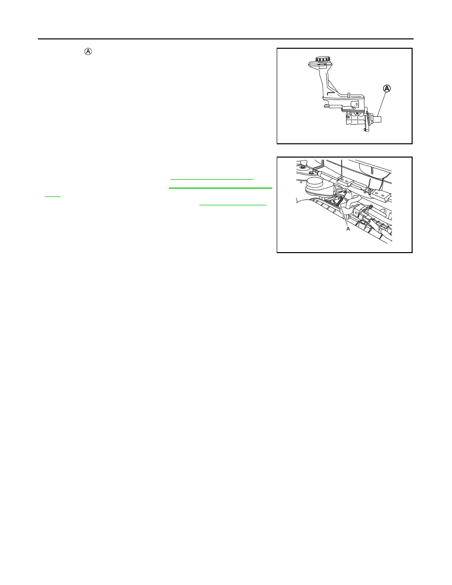
BRAKE MASTER CYLINDER
• The piston
of the master cylinder assembly is exposed. Never
damage it when handling the master cylinder.
• Check that no dirt and dust are present on the piston before instal-
lation. Clean it with new brake fluid if necessary.
• The piston may drop off when pulled strongly. Never hold the pis-
ton. Hold the cylinder body when handling the master cylinder
assembly.
• Never deform or bend the brake tubes.
• Temporarily tighten the brake tube flare nut to the master cylinder
assembly by hand. Then tighten it to the specified torque with a
flare nut torque wrench (A). Refer to
• Perform the air bleeding. Refer to
• Perform inspection after installation. Refer to
Disassembly and Assembly
INFOID:0000000010838520
DISASSEMBLY
CAUTION:
• Never disassemble the cylinder body.
• Remove the reservoir tank only when necessary.
• Never drop parts to remove. Replace new parts when dropping.
1.
Fix the master cylinder assembly to a vise.
CAUTION:
• Always set copper plates or cloth between vise grips when fixing the cylinder body to a vise.
• Never overtighten the vise.
2.
Remove the reservoir tank mounting screw.
3.
Remove the reservoir tank and grommet from the cylinder body.
ASSEMBLY
CAUTION:
• Never use mineral oils such as kerosene or gasoline and rubber grease during the cleaning and
assembly process.
• Never allow foreign matter (e.g. dust) and oils other than brake fluid to enter the reservoir tank.
• Never drop when installing. The parts must not be reused if they are dropped.
1.
Apply new brake fluid to the grommet and install it to the cylinder body.
CAUTION:
Never reuse grommets.
2.
Install the reservoir tank to the cylinder body.
3.
Fix the cylinder body to a vise.
CAUTION:
JSFIA2382ZZ
JSFIA2238ZZ