содержание .. 1117 1118 1119 1120 ..
Nissan X-Trail 32. Manual - part 1119
ENGINE ASSEMBLY
EM-373
< UNIT REMOVAL AND INSTALLATION >
[R9M]
C
D
E
F
G
H
I
J
K
L
M
A
EM
N
P
O
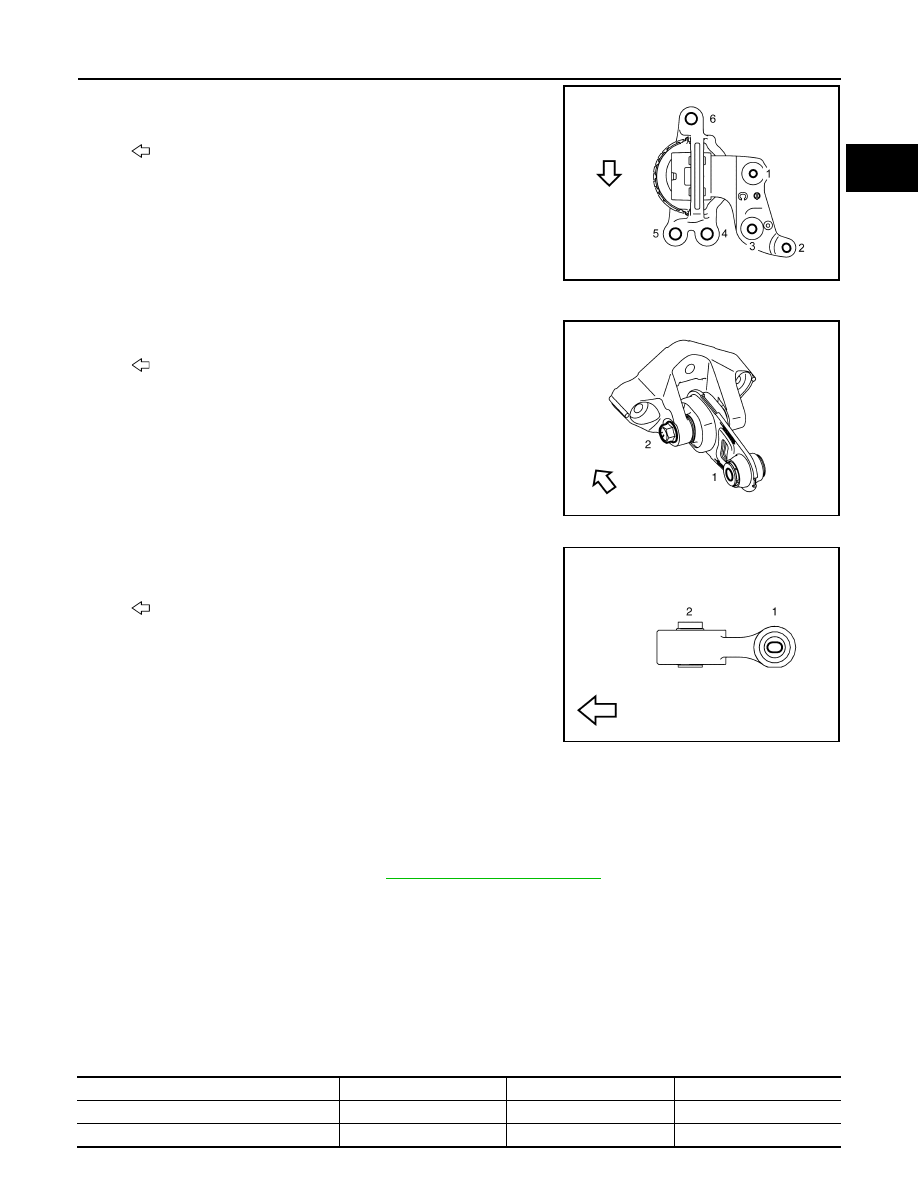
a.
Tighten the bolts in order of No. 1 to 3 as shown in the figure.
(specified torque)
b.
Tighten the bolts in order of No. 4 to 6 as shown in the figure
after removing the jack. (specified torque)
3.
Install the rear torque bolts as follows:
a.
Tighten the bolts as shown in the figure (specified torque).
4.
Install the upper torque rod bolt (RH).
• Tighten the bolts in order of No. 2 to 1 as shown in the figure.
(specified torque)
Inspection
INFOID:0000000010784355
INSPECTION AFTER INSTALLATION
Inspection for Leaks
• Before starting engine, check oil/fluid levels including engine coolant and engine oil. If less than required
quantity, fill to the specified level. Refer to
MA-23, "Fluids and Lubricants"
.
• Use procedure below to check for fuel leakage.
- Turn ignition switch “ON” (with engine stopped). With fuel pressure applied to fuel piping, check for fuel leak-
age at connection points.
- Start engine. With engine speed increased, check again for fuel leakage at connection points.
• Run engine to check for unusual noise and vibration.
• Warm up engine thoroughly to make sure there is no leakage of fuel, exhaust gases, or any oil/fluids includ-
ing engine oil and engine coolant.
• Bleed air from lines and hoses of applicable lines, such as in cooling system.
• After cooling down engine, again check oil/fluid levels including engine oil and engine coolant. Refill to the
specified level, if necessary.
Summary of the inspection items:
: Vehicle front
JPBIA6995ZZ
: Vehicle front
JPBIA6935ZZ
: Vehicle front
JSBIA4537ZZ
Items
Before starting engine
Engine running
After engine stopped
Engine coolant
Level
Leakage
Level
Engine oil
Level
Leakage
Level