содержание .. 1115 1116 1117 1118 ..
Nissan X-Trail 32. Manual - part 1117
ENGINE ASSEMBLY
EM-365
< UNIT REMOVAL AND INSTALLATION >
[R9M]
C
D
E
F
G
H
I
J
K
L
M
A
EM
N
P
O
UNIT REMOVAL AND INSTALLATION
ENGINE ASSEMBLY
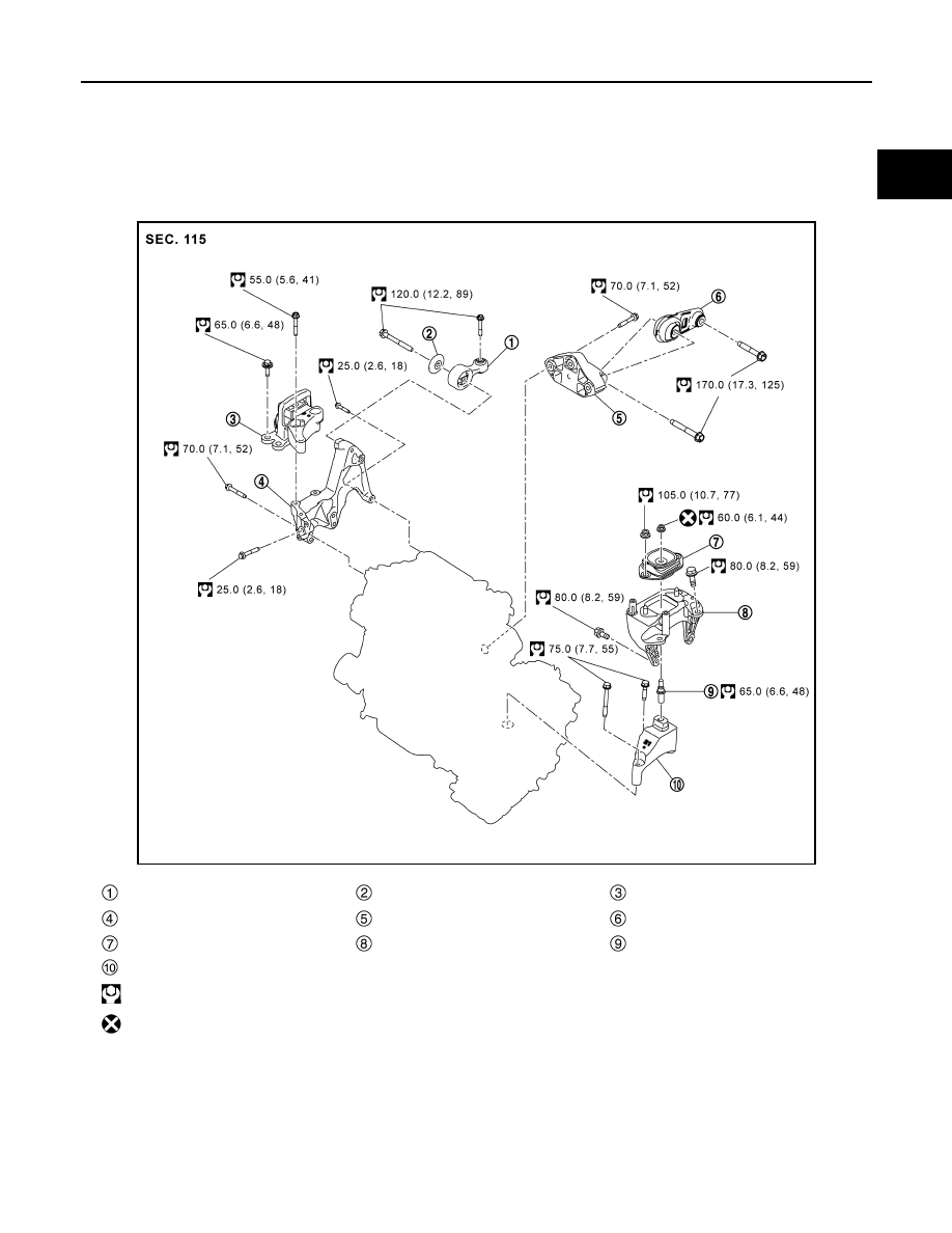
Exploded View
INFOID:0000000010784353
M/T models
JPBIA6927GB
Upper torque rod
Mass damper
Engine mounting insulator (RH)
Engine mounting bracket (RH)
Rear torque rod bracket
Rear torque rod
Engine mounting insulator (LH)
Engine mounting frame support (LH)
Stud bolt
Engine mounting bracket (LH)
: N·m (kg-m, ft-lb)
: Always replace after every disassembly.