содержание .. 1113 1114 1115 1116 ..
Nissan X-Trail 32. Manual - part 1115
CAMSHAFT
EM-357
< REMOVAL AND INSTALLATION >
[R9M]
C
D
E
F
G
H
I
J
K
L
M
A
EM
N
P
O
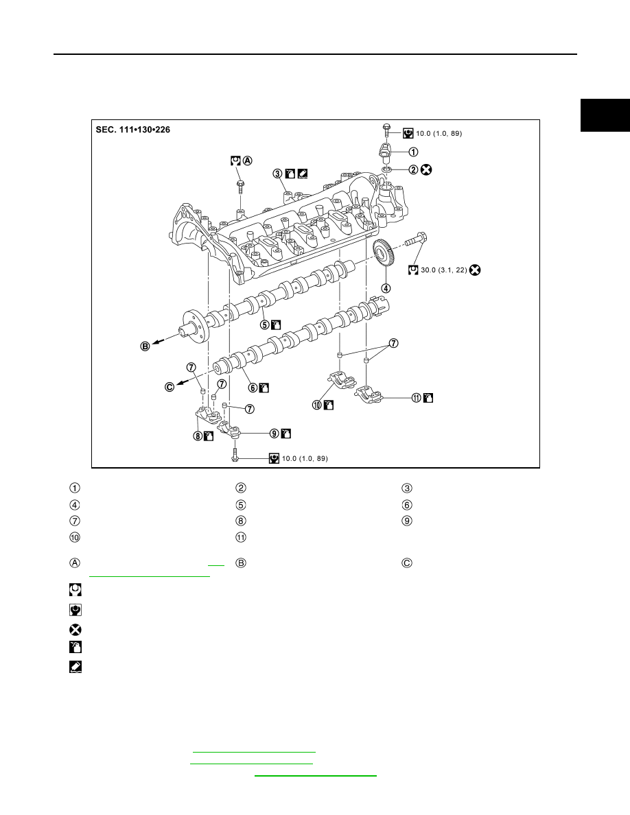
CAMSHAFT
Exploded View
INFOID:0000000010784348
Removal and Installation
INFOID:0000000010784349
REMOVAL
1.
Remove the following parts.
• Oil separator: Refer to
• Fuel injector: Refer to
• Engine slinger (front side): Refer to
Camshaft position sensor
O-ring
Cylinder head housing
Fuel pump gear
Exhaust camshaft
Intake camshaft
Camshaft bracket pin
Camshaft bracket
Camshaft bracket
Camshaft bracket
Camshaft bracket
Comply with the installation proce-
dure when tightening. Refer to
347, "Removal and Installation"
To exhaust camshaft sprocket
To intake camshaft sprocket
: N·m (kg-m, ft-lb)
: N·m (kg-m, in-lb)
: Always replace after every disassembly.
: Should be lubricated with oil.
: Sealing point
JPBIA6955GB