содержание .. 561 562 563 564 ..
Nissan Primera P12. Manual - part 563
LAN-164
[CAN]
CAN SYSTEM (TYPE 30)
Circuit Check Between ESP/TCS/ABS Control Unit and Steering Angle Sensor
EKS00ASC
1.
CHECK CONNECTOR
1.
Turn ignition switch OFF.
2.
Disconnect the negative battery cable.
3.
Check following terminals and connector for damage, bend and loose connection. (connector-side and
harness-side)
●
Harness connector B101
●
Harness connector M87
OK or NG
OK
>> GO TO 2.
NG
>> Repair terminal or connector.
2.
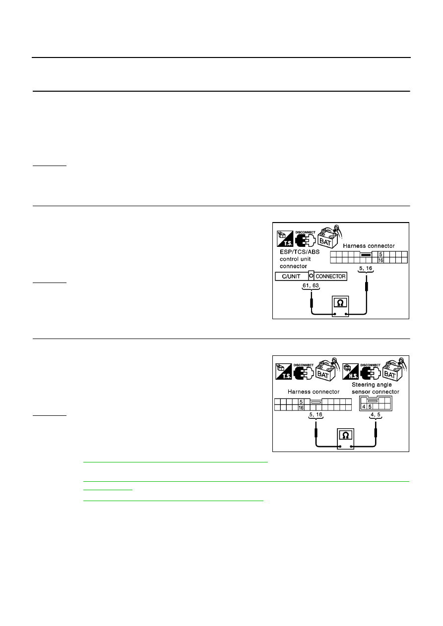
CHECK HARNESS FOR OPEN CIRCUIT
1.
Disconnect ESP/TCS/ABS control unit connector and harness connector B101.
2.
Check continuity between ESP/TCS/ABS control unit harness
connector B109 terminals 61 (L), 63 (R) and harness connector
B101 terminals 5 (L), 16 (R).
OK or NG
OK
>> GO TO 3.
NG
>> Repair harness.
3.
CHECK HARNESS FOR OPEN CIRCUIT
1.
Disconnect steering angle sensor connector.
2.
Check continuity between harness connector M87 terminals 5
(L), 16 (R) and steering angle sensor harness connector M33
terminals 4 (L), 5 (R).
OK or NG
OK
>> Reconnect all connectors to perform “SELF-DIAG
RESULTS” and “DATA MONITOR” for “ENGINE”,
“ABS”, and “SMART ENTRANCE” displayed on CON-
SULT-II. Refer to the following:
●
EC-83, "DTC U1000 CAN COMMUNICATION LINE"
for “ENGINE”
●
BRC-94, "Inspection 15 CAN Communication Circuit, ESP/TCS/ABS Control Unit and Steering
Angle Sensor"
for “ABS”
●
EC-83, "DTC U1000 CAN COMMUNICATION LINE"
for “SMART ENTRANCE”
NG
>> Repair harness.
61(L) – 5(L)
: Continuity should exist.
63(R) – 16(R)
: Continuity should exist.
PKIA0867E
5(L) – 4(L)
: Continuity should exist.
16(R) – 5(R)
: Continuity should exist.
PKIA0869E