содержание .. 559 560 561 562 ..
Nissan Primera P12. Manual - part 561
LAN-156
[CAN]
CAN SYSTEM (TYPE 29)
9.
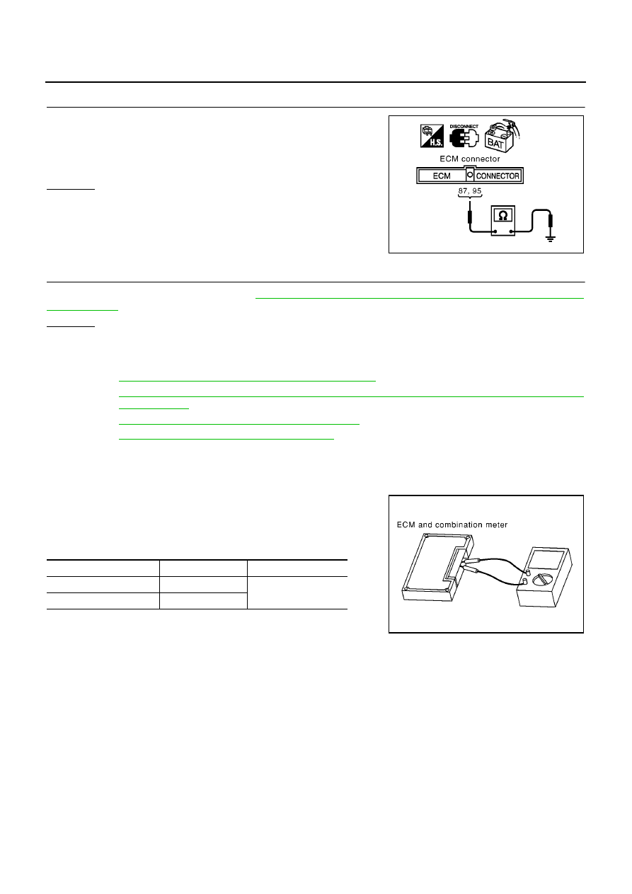
CHECK HARNESS FOR SHORT CIRCUIT
Check continuity between ECM harness connector F119 terminals
95 (L), 87 (R) and ground.
OK or NG
OK
>> GO TO 10.
NG
>> Repair harness between ECM and harness connector
F12.
10.
ECM / COMBINATION METER INTERNAL CIRCUIT INSPECTION
Check components inspection. Refer to
LAN-156, "ECM / COMBINATION METER INTERNAL CIRCUIT
OK or NG
OK
>> Reconnect all connectors to perform “SELF-DIAG RESULTS” and “DATA MONITOR” for
“ENGINE”, “ABS”, “AIR PRESSURE MONITOR”, and “SMART ENTRANCE” displayed on CON-
SULT-II. Refer to the following:
●
EC-83, "DTC U1000 CAN COMMUNICATION LINE"
for “ENGINE”
●
BRC-94, "Inspection 15 CAN Communication Circuit, ESP/TCS/ABS Control Unit and Steering
Angle Sensor"
for “ABS”
●
WT-23, "Inspection 4: CAN Communication Line"
for “AIR PRESSURE MONITOR”
●
BCS-23, "CAN Communication Line Check"
for “SMART ENTRANCE”
NG
>> Replace ECM and/or Combination meter.
Component Inspection
EKS00AS7
ECM / COMBINATION METER INTERNAL CIRCUIT INSPECTION
●
Remove ECM and Combination meter from vehicle.
●
Check resistance between ECM terminals 95 and 87.
●
Check resistance between Combination meter terminals 30 and
31.
95 (L) – ground
: Continuity should not exist.
87 (R) – ground
: Continuity should not exist.
MKIB0610E
Unit
Terminal
Resistance value (
Ω
)
ECM
95 – 87
Approx. 108 - 132
Combination meter
30 – 31
PKIA0830E