Nissan Primera P12. Manual - part 559


  Главная      Nissan     Nissan Primera P12 - Service Manual


поиск по сайту            


содержание   ..  557  558  559  560   ..


Nissan Primera P12. Manual - part 559


LAN-148

[CAN]

CAN SYSTEM (TYPE 29)

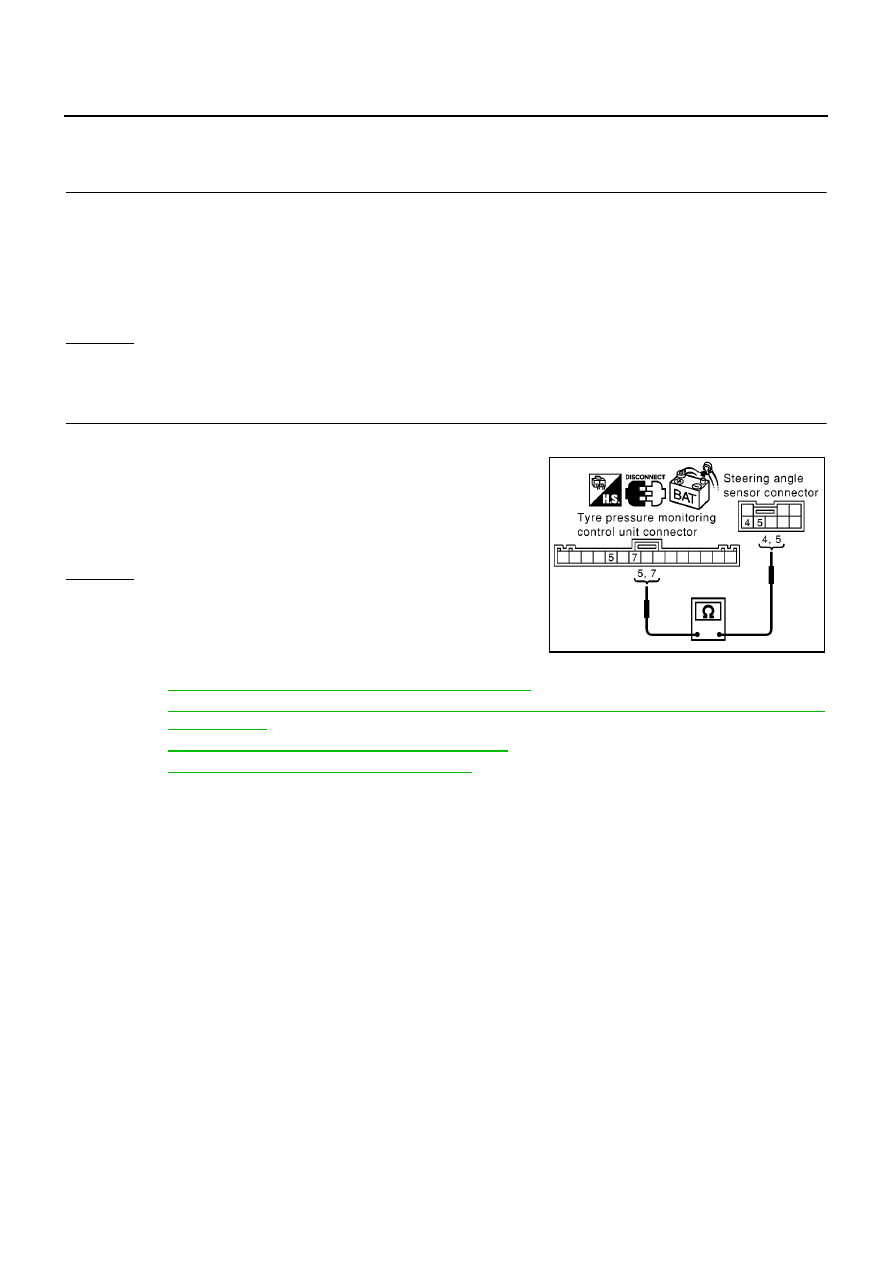
Circuit Check Between Tyre Pressure Monitoring Control Unit and Steering
Angle Sensor

EKS00ARY

1.

CHECK CONNECTOR

1.

Turn ignition switch OFF.

2.

Disconnect the negative battery cable.

3.

Check following terminals and connector for damage, bend and loose connection. (sensor side, control
unit side and harness side)

Steering angle sensor

Tyre pressure monitoring control unit

OK or NG

OK

>> GO TO 2.

NG

>> Repair terminal or connector.

2.

CHECK HARNESS FOR OPEN CIRCUIT

1.

Disconnect tyre pressure monitoring control unit connector and steering angle sensor connector.

2.

Check continuity between tyre pressure monitoring control unit
harness connector M96 terminals 7 (L), 5 (R) and steering angle
sensor harness connector M33 terminals 4 (L), 5 (R).

OK or NG

OK

>> Reconnect all connectors to perform “SELF-DIAG

RESULTS” and “DATA MONITOR” for “ENGINE”,
“ABS”, “AIR PRESSURE MONITOR”, and “SMART
ENTRANCE” displayed on CONSULT-II. Refer to the
following:

EC-83, "DTC U1000 CAN COMMUNICATION LINE"

for “ENGINE”

BRC-94, "Inspection 15 CAN Communication Circuit, ESP/TCS/ABS Control Unit and Steering
Angle Sensor"

for “ABS”

WT-23, "Inspection 4: CAN Communication Line"

for “AIR PRESSURE MONITOR”

BCS-23, "CAN Communication Line Check"

for “SMART ENTRANCE”

NG

>> Repair harness.

7 (L) – 4 (L)

: Continuity should exist.

5 (R) – 5 (R)

: Continuity should exist.

PKIA0884E

CAN SYSTEM (TYPE 29)

LAN-149

[CAN]

C

D

E

F

G

H

I

J

L

M

A

B

LAN

Circuit Check Between Steering Angle Sensor and Smart Entrance Control Unit

EKS00ARZ

1.

CHECK CONNECTOR

1.

Turn ignition switch OFF.

2.

Disconnect the negative battery cable.

3.

Check following terminals and connector for damage, bend and loose connection. (control unit side, sen-
sor side and harness side)

Smart entrance control unit

Steering angle sensor

OK or NG

OK

>> GO TO 2.

NG

>> Repair terminal or connector.

2.

CHECK HARNESS FOR OPEN CIRCUIT

1.

Disconnect smart entrance control unit connector and steering angle sensor connector.

2.

Check continuity between smart entrance control unit harness
connector M41 terminals 8 (L), 11 (R) and steering angle sensor
harness connector M33 terminals 4 (L), 5 (R).

OK or NG

OK

>> Reconnect all connectors to perform “SELF-DIAG

RESULTS” and “DATA MONITOR” for “ENGINE”,
“ABS”, “AIR PRESSURE MONITOR”, and “SMART
ENTRANCE” displayed on CONSULT-II. Refer to the
following:

EC-83, "DTC U1000 CAN COMMUNICATION LINE"

for “ENGINE”

BRC-94, "Inspection 15 CAN Communication Circuit, ESP/TCS/ABS Control Unit and Steering
Angle Sensor"

for “ABS”

WT-23, "Inspection 4: CAN Communication Line"

for “AIR PRESSURE MONITOR”

BCS-23, "CAN Communication Line Check"

for “SMART ENTRANCE”

NG

>> Repair harness.

8 (L) – 4 (L)

: Continuity should exist.

11 (R) – 5 (R)

: Continuity should exist.

PKIA0907E

LAN-150

[CAN]

CAN SYSTEM (TYPE 29)

ECM Circuit Check

EKS00AS0

1.

CHECK CONNECTOR

1.

Turn ignition switch OFF.

2.

Disconnect the negative battery cable.

3.

Check following terminals and connector for damage, bend and loose connection. (control module side
and harness side)

ECM

Harness connector F12

Harness connector E62

Harness connector E117

Harness connector B104

OK or NG

OK

>> GO TO 2.

NG

>> Repair terminal or connector.

2.

CHECK HARNESS FOR OPEN CIRCUIT

1.

Disconnect ECM connector.

2.

Check resistance between ECM harness connector F119 termi-
nals 95 (L) and 87 (R).

OK or NG

OK

>> Replace ECM.

NG

>> Repair harness between ESP/TCS/ABS control unit and

ECM.

95 (L) – 87 (R)

: Approx. 108 – 132

MKIB0609E

CAN SYSTEM (TYPE 29)

LAN-151

[CAN]

C

D

E

F

G

H

I

J

L

M

A

B

LAN

ESP/TCS/ABS Control Unit Circuit Check

EKS00AS1

1.

CHECK CONNECTOR

1.

Turn ignition switch OFF.

2.

Disconnect the negative battery cable.

3.

Check following terminals and connector of ESP/TCS/ABS control unit for damage, bend and loose con-
nection. (control unit side and harness side)

OK or NG

OK

>> GO TO 2.

NG

>> Repair terminal or connector.

2.

CHECK HARNESS FOR OPEN CIRCUIT

1.

Disconnect ESP/TCS/ABS control unit connector.

2.

Check resistance between ESP/TCS/ABS control unit harness
connector B109 terminals 61 (L) and 63 (R).

OK or NG

OK

>> Replace ESP/TCS/ABS control unit.

NG

>> Repair harness between Data link connector and ESP/

TCS/ABS control unit.

Tyre Pressure Monitoring Control Unit Circuit Check

EKS00AS2

1.

CHECK CONNECTOR

1.

Turn ignition switch OFF.

2.

Disconnect the negative battery cable.

3.

Check terminals and connector of tyre pressure monitoring control unit for damage, bend and loose con-
nection. (control unit side and harness side)

OK or NG

OK

>> GO TO 2.

NG

>> Repair terminal or connector.

2.

CHECK HARNESS FOR OPEN CIRCUIT

1.

Disconnect tyre pressure monitoring control unit connector.

2.

Check resistance between tyre pressure monitoring control unit
harness connector M96 terminals 7 (L) and 5 (R).

OK or NG

OK

>> Replace tyre pressure monitoring control unit.

NG

>> Repair harness between steering angle sensor and tyre

pressure monitoring control unit.

61 (L) – 63 (R)

: Approx. 54 – 66

PKIA0818E

7 (L) – 5 (R)

: Approx. 54 – 66

PKIA0863E


содержание   ..  557  558  559  560   ..